SHOP MANUAL
DRIVE LINE
Ch 3 page 166 Ch 3 page 167
DRIVE LINE
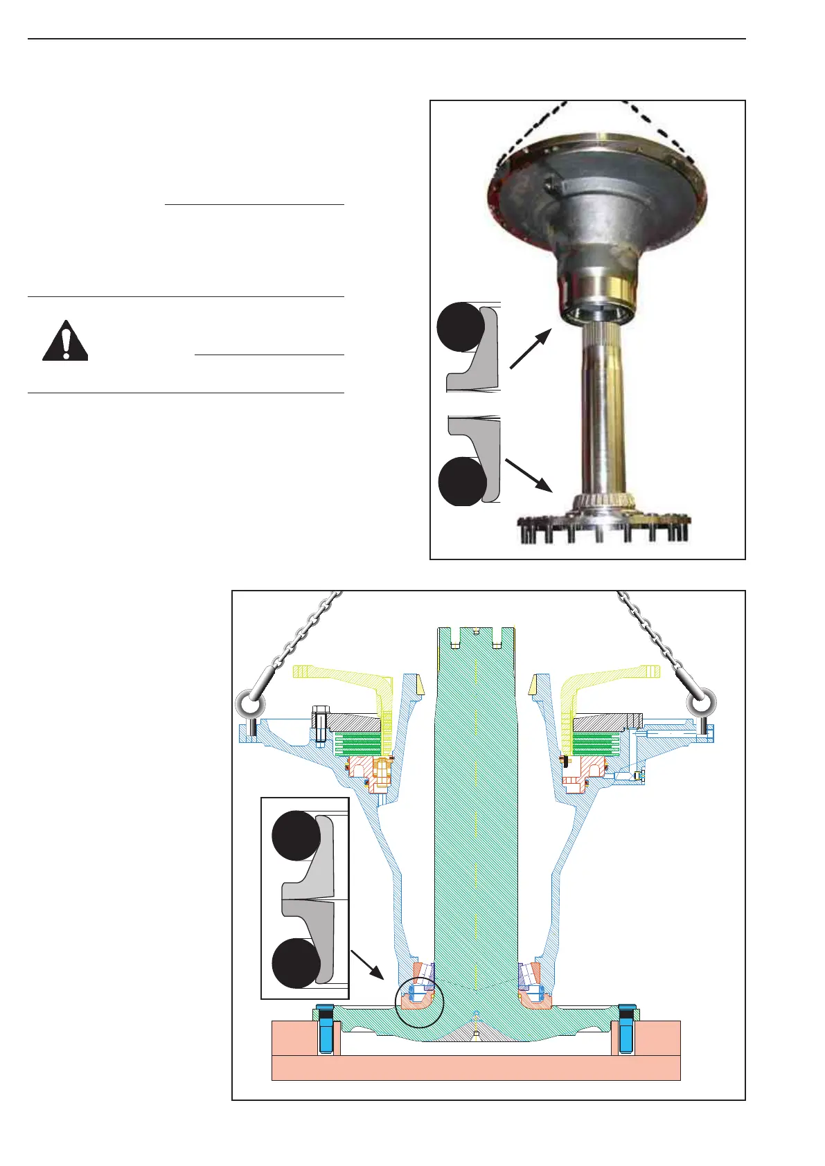
With attention and carefully assemble the hub on the axle.
Be aware of personal injury
Lubricate sealing surfaces.
Be aware and careful of the
seal ring on lower end of
the hub while assembly the
hub to the axle.
Remove lifting device
Prepare stand for the hub work over
Assemble the
wheel bolt.
Use hydraulic press or
sledgehammer.
Preassemble the distance ring
Insert 2 pcs. screws plug and O-r
ing
Lubricate the O-ring and use
locking compound (tread lock)
Tree Bond 5111to lock the
screw plug.
Clean the axle
and apply oil
Assemble the distance ring.
Check the ring is in contact
with the axle flange
ing
ing
are, replace worn rings with new
ings (Only as set)
faces before assembly
Assemble the outer bearing.
Clean the axle and apply oil
before assemble the bearing.
Heat the bearing with
electrical heater or hot oil
Temp 75 - 90°C
(167 - 194°F)
Hold press to the bearing
until cool down
Turn the hub housing
180 ° while assembly
the bearing cup and
the seal
Clean the bearing surface and
assemble the bearing cup
Clean the surface and
assemble the seal ring
Place the hub in assembly rack after assemble
of the bearing cup and the seal ring.
Be careful with the seal ring
Insert the plug
Clean the bearing surface and
assemble the bearing cup
Assemble the guide ring
Pos 23-24
Assemble the piston ring
Pos 21 - 22
Assemble the guide ring
Use glue: Loctite no.406
at both ends.
Lubricate seal area
before inserting the
piston.
Preassemble the Return mechanism- piston
X
1
2
3
4
5
Figure 26
Legend to the sketch:
1 = Pin
2 = Gripping rings
3 = Cup springs
4 = Support shim
5 = Circlip
X = Installation dimension Gripping rings 8.2 +0.3mm
For more details about assembling
of the return mechanism, see
description in the Shop Manual,
front axle, hub assembly.
Place the return mechanism lock ring
Assemble 6 pcs. of the slot pin
into the return mechanism
Slot pin 6x20 DIN 1481
Calculation example:
Measure A.................................. 47,10
Measure B.................................- 6,40
Gives:..........................................= 40,70
Discs unit.................................. - 38,60
Clearance.................................. = 2,10
Allowed clearanse 1,7 - 2,1 mm
B
A
Place the "line up tool"
Moxy part No. 514663
Apply oil to the parts and place the
brake disc, one by one.
Start assembly with outer disc.
1 The outer disc (5 pcs, different thickness available)
2 The inner disc (4 pcs. thickness 4,7 mm)
4.0
4.0
4.0
4.0
3.8
Example
Clean the surface and
place the O-ring
Place the flange
20 pcs . screw M16x50 ISO4017-10.9 EL
Apply locking liquid: Tree bond 1374
Washer 17x30x3 NS-ISO 7089 300HV
Tightening torque: 280 Nm.
0 bar
50 bar
Pressure test:
Increase test pressure up to p = 50 bar and close the
connection to the HP-pump by means the of shut-off v
alve.
During a 5 min. testing time a pressure drop of max.
2 %
Shut of valve
ess is stay on !
Lubricate the parts and
assemble the carrier.
No
w, remove the
e tester,
t lifting device
WARNING
The seal ring is made of specially material
and while assemblying the ring have to be
handle very carefully and surfaces have to
be cleaning well.
NOTE
Figure 497
Figure 498