Version 6.6 19 October 2014
Installation & Operation Manual Contents
List of Figures
Figure 1-1: Mediant 8000 Block Diagram ...............................................................................................31
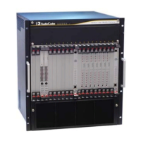
Figure 3-1: Mediant 8000 Front View .....................................................................................................37
Figure 3-2: Mediant 8000 Back View .....................................................................................................38
Figure 4-1: Midplane in Chassis .............................................................................................................39
Figure 5-1: PEM/DC/8K Power Entry Module Panel ..............................................................................41
Figure 5-2: PS/DC/8K Power Supply Module .........................................................................................42
Figure 6-1: FM/8K Fan Tray Module ......................................................................................................43
Figure 8-1: TP-6310 Board Front Panel .................................................................................................47
Figure 9-1: 6310 RTM Front Panel .........................................................................................................50
Figure 9-2: 6310/RTM Redundant Front Panel ......................................................................................51
Figure 10-1: TP-8410 Board Front Panel ...............................................................................................53
Figure 11-1: 8410 RTM Panel ................................................................................................................57
Figure 11-2: 8410/RTM 100-Pin SCSI Connector ..................................................................................58
Figure 11-3: 8410/RTM 68-pin SCSI Connector ....................................................................................59
Figure 11-4: 8410/RTM Redundant Front Panel ....................................................................................61
Figure 12-1: SC Rev.1 Board Panel .......................................................................................................64
Figure 12-2: SC Rev.1 Board Mini DIN 8 Serial Port Connector ............................................................65
Figure 12-3: SC Rev.2 Board Panel .......................................................................................................66
Figure 12-4: SA/RTM Panel ...................................................................................................................69
Figure 12-5: RJ-48c Trunk Connectors ..................................................................................................71
Figure 13-1: ES/6600 Board Panel ........................................................................................................74
Figure 13-2: ES/6600/RTM Panel ..........................................................................................................78
Figure 13-3: ES-2 Board Panel ..............................................................................................................81
Figure 13-4: ES-2 RTM ..........................................................................................................................85
Figure 16-1: Attaching the Chassis to the Rack ...................................................................................101
Figure 16-2: Chassis on the Rack - Front and Side Views ..................................................................102
Figure 16-3: Connecting the Mediant 8000 to a DC Power Supply .....................................................104
Figure 16-4: Securing the PEM Plastic Cover Spacers (Hex) ..............................................................105
Figure 16-5: Secure the PEM Plastic Cover Screws ............................................................................106
Figure 17-1: Using PuTTY for RS-232 Serial Connections ..................................................................110
Figure 17-2: PuTTY RS-232 Serial Connection Settings .....................................................................111
Figure 17-3: Using PuTTY for SSH connection....................................................................................112
Figure 18-1: Connecting the IP Network for an Initial Installation ........................................................121
Figure 19-1: SFP Modules and Their Locks .........................................................................................124
Figure 19-2: T3 - Male Connector MOLEX PN: 73100-0255 ...............................................................125
Figure 20-1: Normal Logic External Alarm Equipment Connection......................................................127
Figure 20-2: Inverse Logic External Alarm Equipment Connection .....................................................128
Figure 23-1: Sample MO Tree Hierarchy .............................................................................................161
Figure 23-2: Graphical EMS Status Screen .........................................................................................163
Figure 23-3: Textual EMS Status Screen .............................................................................................163
Figure 23-4: Navigation Pane and Info Panel in EMS ..........................................................................164
Figure 23-5: EMS Configuration Pane .................................................................................................166
Figure 23-6: Example Settings Screen-Trunk Settings ........................................................................166
Figure 23-7: EMS Alarm Browser .........................................................................................................167
 Loading...
