Version 6.6 121 October 2014
Installation & Operation Manual 18. Connecting to the IP Network
Note: The above procedure ensures that the Media Gateway software
configuration fully matches the IP network configuration and must be performed
even after a “minor” change to the basic network configuration (e.g. change of SC
board’s hostname).
14. Repeat steps 1-13 on the 2
nd
SC board. Ensure to configure a different hostname
and IP address on each SC board.
18.3 Connecting IP Network Cables
IP Network connectors are located on the ES RTM modules in the rear of the Mediant
8000 chassis. See 'ES/6600/RTM Rear Transition Module' on page 78 and 'ES/ACS-
38-SINGLE ES (Ethernet Switch) Board' on page 80 for a detailed connectors
description.
The Mediant 8000 software by default uses a “single subnet without VLAN tagging”
configuration. Therefore two external redundant Layer 3 switches or routers should be
connected to port 20 on both the ES RTM modules. Use CAT 5 or better 1Gb Ethernet
cables for this connection. Ensure that the CAT 5 cables that you use are threaded
according to customers' exterior cable management guides.
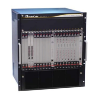
Figure
18-1: Connecting the IP Network for an Initial Installation
 Loading...
