Version 6.6 71 October 2014
Installation & Operation Manual 12. System Controller (SC) Board
12.3.2 SA/RTM Terminal Block Connector
The SA/RTM board provides a Terminal Block Connector that may be used for
connecting the Telco alarm equipment. Three dry contacts – COM (Common), NO
(Normally Open) and NC (Normally Closed) – are provided for each alarm.
Table
12-6: SA/RTM Terminal Block Connector
Alarm
Type
Description Connector Types Number of Connectors
CRT Critical COM, NC, NO 3
MJR Major COM, NC, NO 3
MNR Minor COM, NC, NO 3
USR User Defined COM (x2)*, NC, NO, *IN
1, *IN 2
6
*One COM connector and IN 1 and IN 2 connnectors are for future use.
To mute the Telco alarm relay devices attached to the SA/RTM Terminal Block, use
the ACO Alarm push button located below the Chassis Alarm Indicators LEDs.
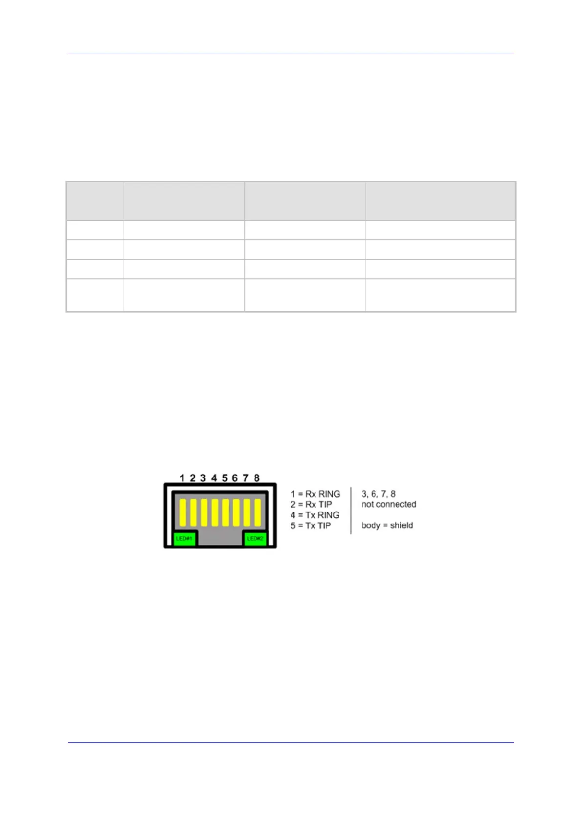
12.3.3 SA/RTM BITS (RJ48-c) Pin Signal Interface (Optional)
The SA/RTM board with a resident Timing Module provides two BITS (RJ48-c)
Interfaces for connecting to the external Building Integrated Timing Supply (BITS)
equipment. The following table describes the signal interface of the connector.
Figure
12-5: RJ-48c Trunk Connectors

 Loading...


