SHOP MANUAL
TRANSMISSION
Ch 2 page 46 Ch 2 page 47
TRANSMISSION
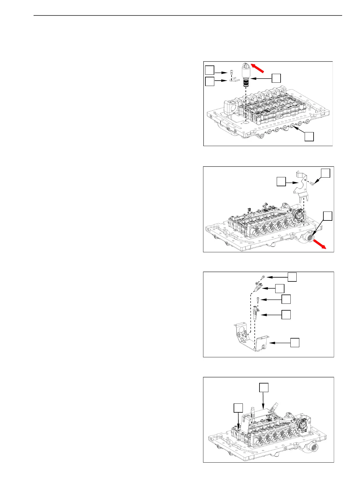
Insert the dierential lock solenoid valve (1) with bracket (2)
into the valve block and x it with the cylindrical screws (3).
Tightening torque (M6/8.8x12) M
A
= 9.5 Nm
Ensure correct installation position of solenoid valve (plug
connection) - see arrow.
Fit all screw plugs M12x1.5 with O-ring 9.5x2 (4).
Tightening torque M
A
= 12 Nm
Insert the wiring harness (1) into the duct plat from the op-
posite side, attach it with fixing bracket (2) and fasten it with
the cylindrical screws (3).
Tightening torque (M6/8.8x12) M
A
= 9.5 Nm
Close the lockings of plug connections for wiring
harness/pressure controllers/dierential lock solenoid valve.
Fasten the speed sensors (1 and 2) to the xing plate (3) using
the cylindrical screws (4).
Tightening torque (M6/8.8x12) M
A
= 9.5 Nm
Legend of speed sensors:
1 = speed sensor - n1 turbine
2 = speed sensor - n2 primary step
Bring the speed sensors into contact position with the valve
block using the fixing plate (1) and fix them with the Torx
screws (2).
Tightening torque (M6/10.9x50) M
A
= 9.5 Nm
Figure 103
Figure 101
Figure 102
Figure 104