SHOP MANUAL
TRANSMISSION
Ch 2 page 48 Ch 2 page 49
TRANSMISSION
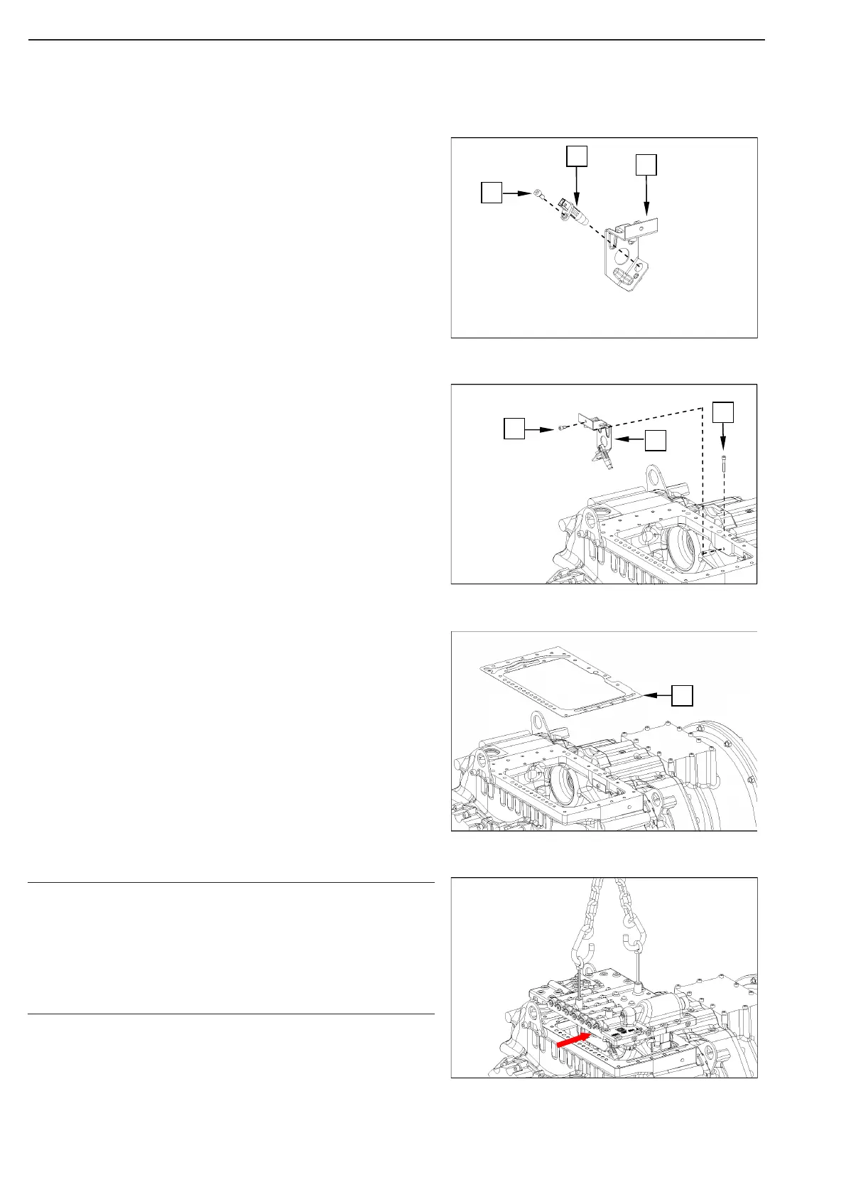
Fix the speed senor (2) to the fixing plate (3) using the cylidri-
cal screw (1)
Tightening torque (M6/8.8x12) MA = 9.5 Nm
Legend of speed sensor:
2 = speed sensor – n3 secondary step.
Bring the speed sensor into contact position with the transmis-
sionscrews
housing using the fixing plate (1) and fix it with the cylindrical
screw (2 and 3).
2 = Tightening torque (M6/8.8x12) MA = 9.5 Nm
3 = Tightening torque (M6/8.8x35) MA = 9.5 Nm
Bring seal (1) into contact position.
Mount two eyebolts, use a lifting tackle to bring the duct
plate (1) into contact position until it is possible to close
the bayonet locking of wiring harness – shifting
block I / wiring harness - shifting block II, as well as the
lockings of dierential lock solenoid valve andspeed sen-
sor (see arrow and gure 107).
NOTE
Figure 108
Figure 107
Figure 106
Figure 105