SHOP MANUAL
DRIVE LINE
Ch 3 page 22 Ch 3 page 23
DRIVE LINE
2
2
1
2
3
4
6
5
1
7
1
2
3
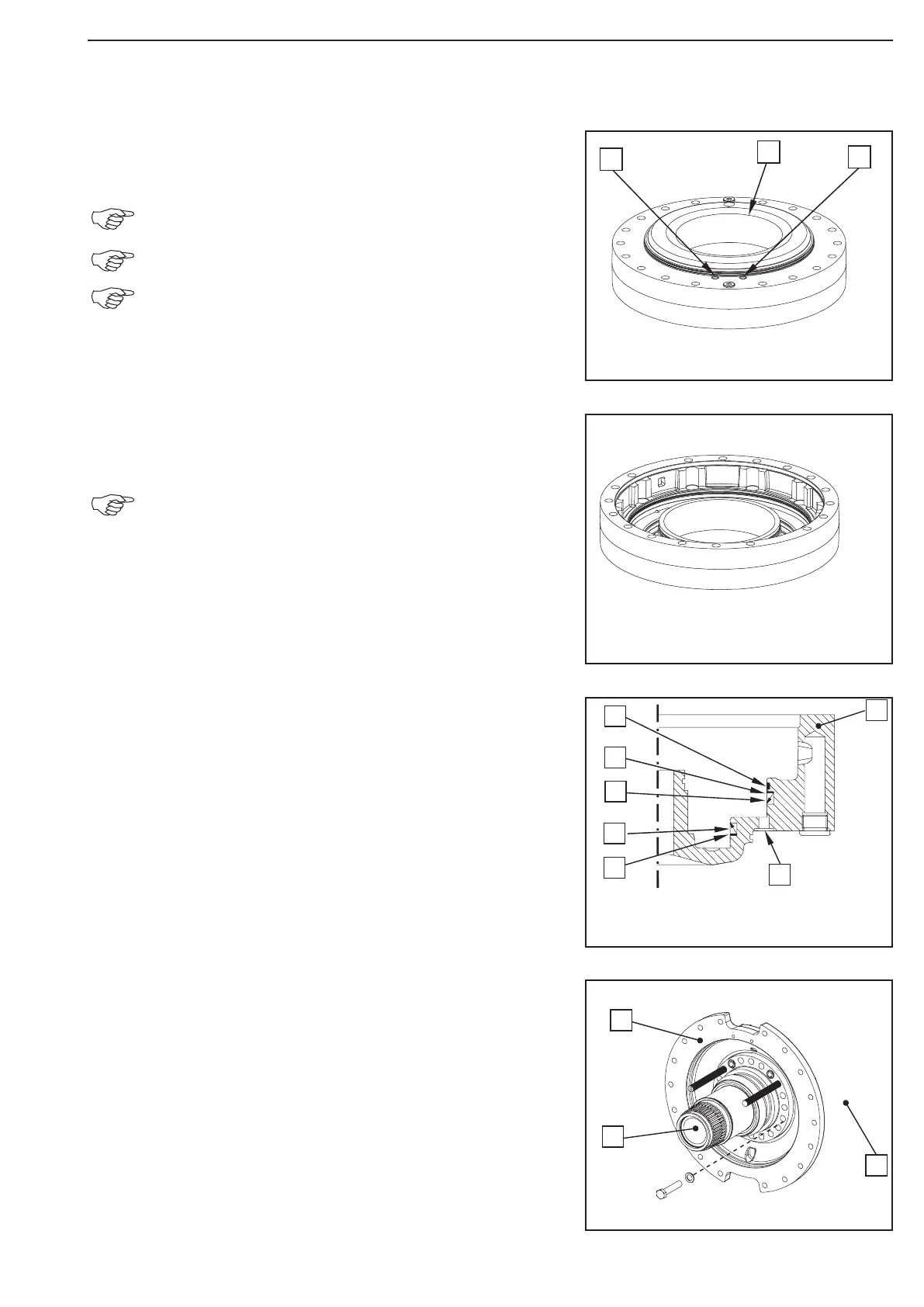
By means of compressed air press the piston out of the brake
housing (1).
By means of the lifting tackle rotate the brake carrier by
180°!
See the sketch for connections (2)!
Cover the bore (1) with the hand (pressure build-up)!
Remove the guide ring, the support rings and U-rings from the
annular grooves of the brake housing.
See below sketch for installation position of
the single parts!
Legend to the sketch:
1 = Brake housing
2 = Guide ring
3 = Backup ring
4 = U-Ring
5 = U-Ring
6 = Backup ring
7 = Pressure connection
Loosen the bolt connection hub carrier (2), brake carrier (1) and
axle casing (3).
Install adjusting screws.
(S) Adjusting screws 514650
Figure 37
Figure 38
Figure 39
Figure 40