SHOP MANUAL
DRIVE LINE
Ch 3 page 42 Ch 3 page 43
DRIVE LINE
1
1
2
4
3
2
1
Example:
Dim. I e.g..…..................................... 9.40 mm
Dim. II e.g. ........................................ - 4.00 mm
Difference ........................................ = 5.40 mm
required axial clearance .............e.g. - 0.40 mm
Result = Thrust washer s = 5.00 mm
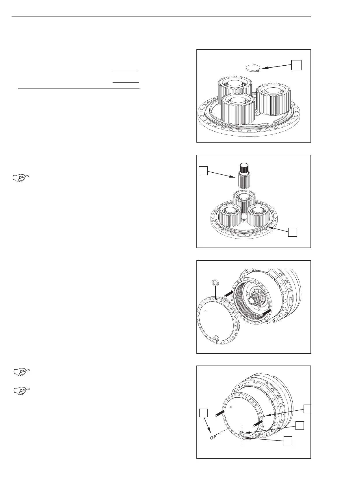
Fix the thrust washer (1) with grease into the
planet carrier.
Insert the sun gear shaft (1).
Insert the O-Ring (2) into the annular ring and grease it.
With the lifting tackle insert the preassembled planet carrier into
the ring gear and locate it at the hub until contact.
(S) Lifting tackle 514658
(S) Adjusting screws 505759
Observe the radial installation position of the planet car
rier (see Fig. 116 and 117)!
The through hole (1) in the hub (existing only 1x) must
be aligned to the filler and drain hole (2) respectively of
the planet carrier.
Also observe the markings made (3) at the
disassembly !
Figure 116
Figure 115
Figure 114
Figure 113