SHOP MANUAL
DRIVE LINE
Ch 3 page 96 Ch 3 page 97
DRIVE LINE
1. 2.2 DIFFERENTIAL DL-1600, Interlock value 45%
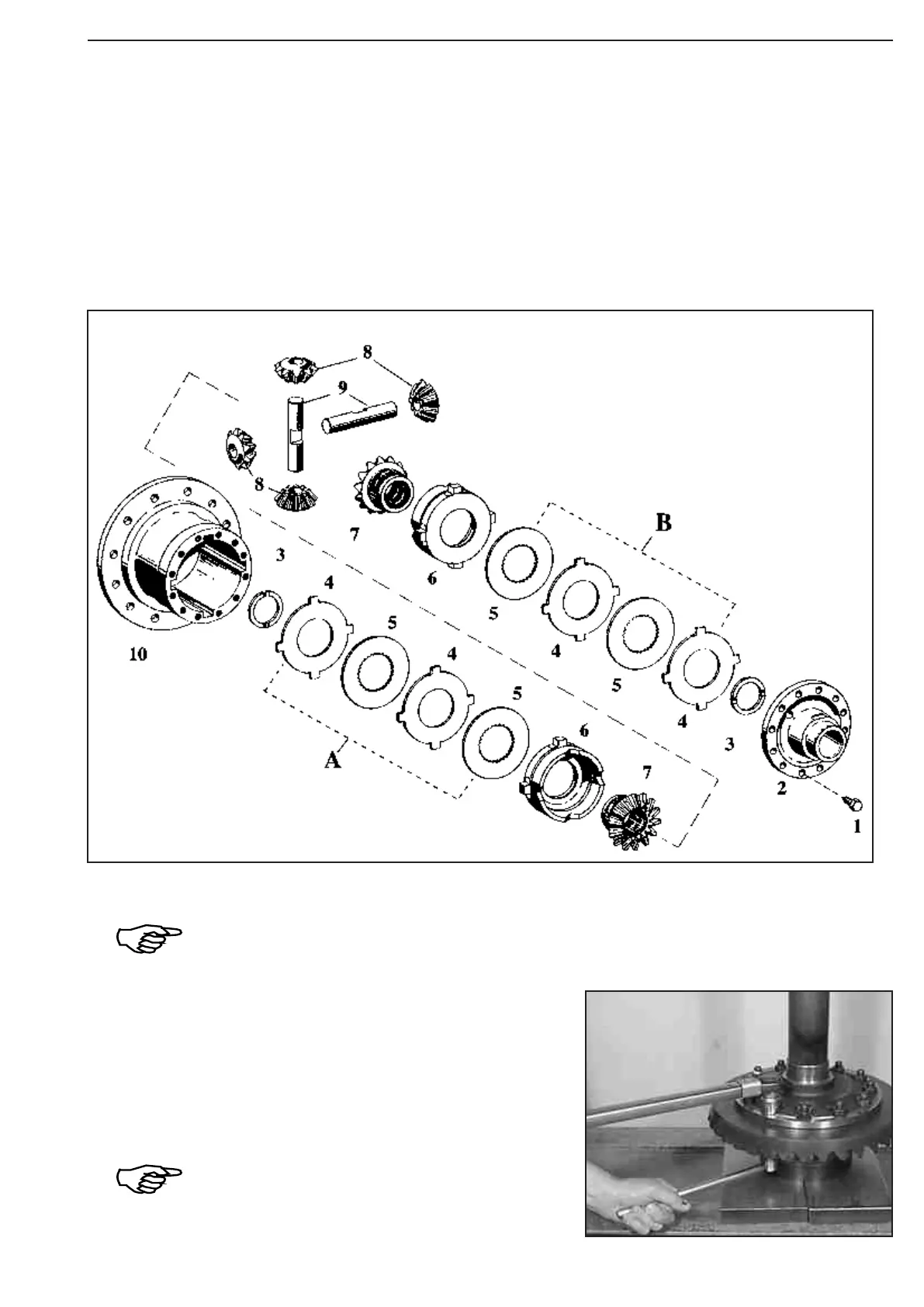
The following Perspective Illustration (figure 269) shows the components of the Differential and its installation
location.
41 = Strain bolts 38 = Thrust ring
43 = Housing cover 37 = Side gear
42 = Thrust washer 35 = Differential bevel gear
40 = Outer plate (optional) 36 = Differential axle
39 = Inner plate 44 = Differential housing
For the adjustment of the assembly play of the inner parts (see Figure 279 ... Example B), outer
plates (4) of different thickness are available (s = 2,9 ... 3,1 mm).
With that, the outer plates must be selected in such a way that the height of the plate packs A
and B is identical on both sides of the differential !
Fasten crown wheel on the differential case, using socket head
screws and castle nuts.
M20x1,5/10
Loctite No. 262
Torque limit .................................. » 620 Nm
Now, secure castle nuts by means of cotter pins !
Figure 270
Figure 269