SHOP MANUAL
DRIVE LINE
Ch 3 page 126 Ch 3 page 127
DRIVE LINE
Mount two adjusting screws (S) and insert the differential
cover by means of the lifting device.
(S) Locating pins 504722
(S) Inner extractor 532218
(S) Eye nut 532220
Preload the differential by means of the press and bolt with
new locking screws.
Tightening torque (M16/12.9) MA = 400 Nm
(S) Pressure piece 532231
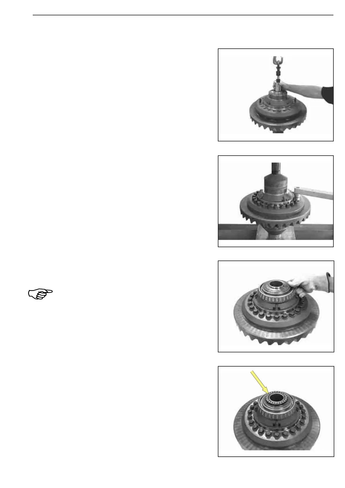
Heat both tapered roller bearings and insert until contact is
obtained.
Adjust tapered roller bearing after cooling down.
Insert axial roller cage (see arrow).
Reassembly
Figure 379
Figure 378
Figure 377
Figure 376