SHOP MANUAL
DRIVE LINE
Ch 3 page 130 Ch 3 page 131
DRIVE LINE
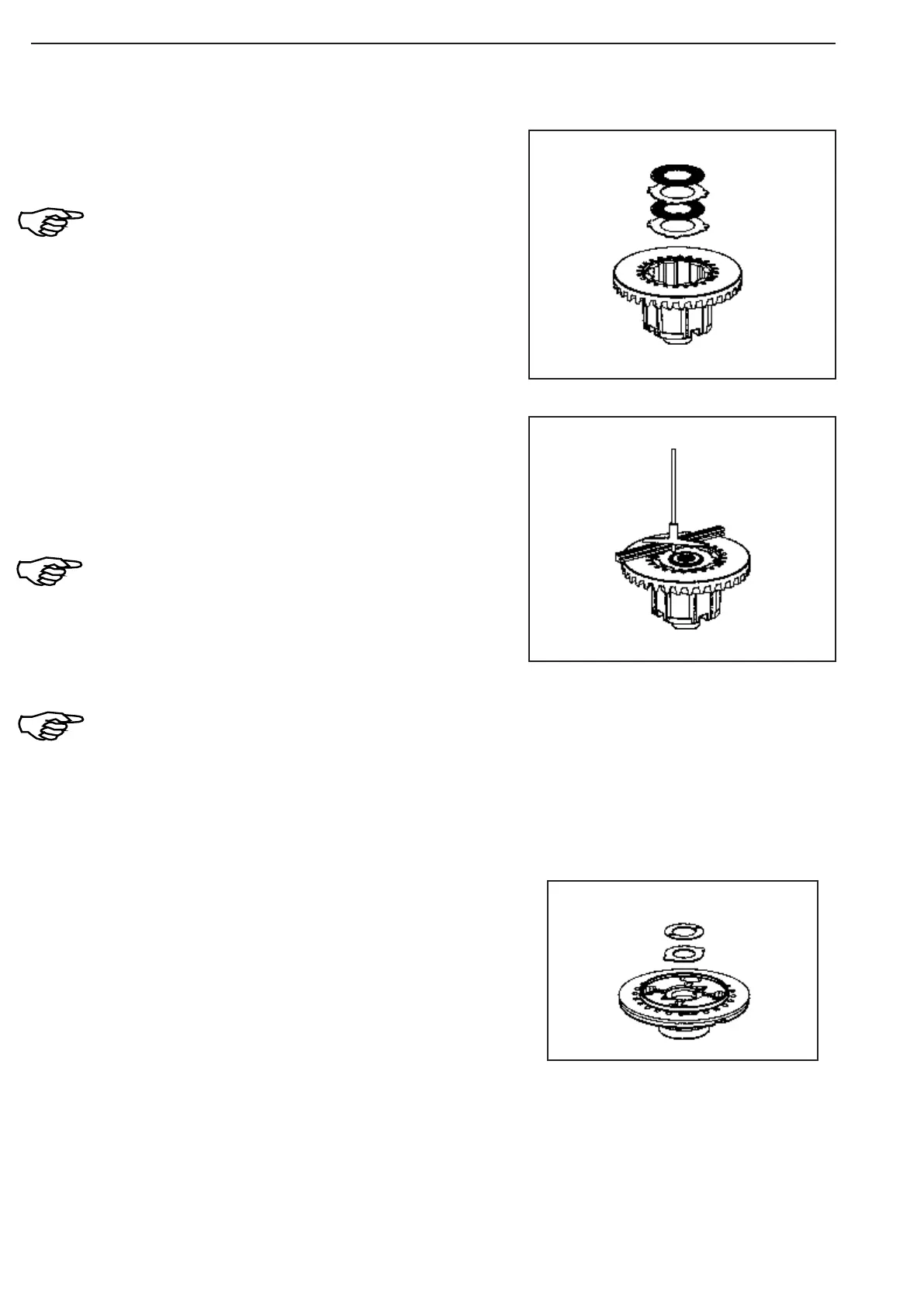
Mount inner and outer disks in alternating order, starting
with an inner disk.
The installation clearance of the internal parts is
corrected by mounting outer disks with different
thicknesses!
The difference in thickness between the left and the
right disk package may only be 0.1 mm at maximum!!
Setting of dimension „A“ 6.7 … 7.1 mm
(assembly clearance)
Measure dimension A, from the front face of the crown
wheel to the plane face of the outer disk.
Dimension A e.g. 6.80 mm
Dimension A must be between 6.7 and 7.1 mm.
It is recommended to try to achieve the lower value.
Correction of dimension A by installing suitable outer
disks.
Take care that the difference in thickness between the
left and the right disk package may only be 0.1 mm at
maximum!
Fix the thrust washers into the housing cover by means of
grease.
Reassembly
Figure 390
Figure 389
Figure 388