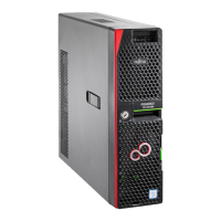
Upgrade and Maintenance Manual RX2540 M4
7.3.12.4 Installing the new connector card . . . . . . . . . . . . . . 176
7.3.12.5 Concluding steps . . . . . . . . . . . . . . . . . . . . . . 177
7.4 2.5-inch HDD/SSD configurations . . . . . . . . . . . . . . 177
7.4.1 Configuration with up to eight HDD/SSD modules . . . . . . . 177
7.4.2 Configuration with up to 16 HDD/SSD modules . . . . . . . . 178
7.4.3 Configuration with up to 24 HDD/SSD modules . . . . . . . . 179
7.4.4 Configuration with additional PCIe-SSDs . . . . . . . . . . . . 180
7.4.5 Configuration with 4x 2.5-inch SAS HDD/SSDs or PCIe SSDs
accessible from the rear side . . . . . . . . . . . . . . . . . . 181
7.4.6 Installing 2.5-inch HDD/SSD modules . . . . . . . . . . . . . 182
7.4.6.1 Preliminary steps . . . . . . . . . . . . . . . . . . . . . . 182
7.4.6.2 Removing a 2.5-inch dummy module . . . . . . . . . . . . 182
7.4.6.3 Installing a 2.5-inch HDD/SSD module . . . . . . . . . . . 183
7.4.6.4 Concluding steps . . . . . . . . . . . . . . . . . . . . . . 184
7.4.7 Removing 2.5-inch HDD/SSD modules . . . . . . . . . . . . . 185
7.4.7.1 Preliminary steps . . . . . . . . . . . . . . . . . . . . . . 185
7.4.7.2 Removing a 2.5-inch HDD/SSD module . . . . . . . . . . 186
7.4.7.3 Installing a 2.5-inch dummy module . . . . . . . . . . . . . 186
7.4.7.4 Concluding steps . . . . . . . . . . . . . . . . . . . . . . 186
7.4.8 Replacing a 2.5-inch HDD/SSD module . . . . . . . . . . . . 187
7.4.8.1 Preliminary steps . . . . . . . . . . . . . . . . . . . . . . 188
7.4.8.2 Removing a 2.5-inch HDD/SSD module . . . . . . . . . . 188
7.4.8.3 Installing a 2.5-inch HDD/SSD module . . . . . . . . . . . 188
7.4.8.4 Concluding steps . . . . . . . . . . . . . . . . . . . . . . 188
7.4.9 Replacing a 8 x 2.5-inch HDD backplane . . . . . . . . . . . . 189
7.4.9.1 Preliminary steps . . . . . . . . . . . . . . . . . . . . . . 189
7.4.9.2 Disconnecting the HDD backplane . . . . . . . . . . . . . 189
7.4.9.3 Removing the HDD backplane . . . . . . . . . . . . . . . 191
7.4.9.4 Installing the HDD backplane . . . . . . . . . . . . . . . . 191
7.4.9.5 Connecting the HDD backplane . . . . . . . . . . . . . . . 192
7.4.9.6 Connecting the SAS cables (one 2.5-inch HDD backplane) 193
7.4.9.7 Connecting the SAS cables (two 2.5-inch HDD backplanes) 195
7.4.9.8 Connecting the SAS cables (three 2.5-inch HDD
backplanes) . . . . . . . . . . . . . . . . . . . . . . . . . 197
7.4.9.9 Connecting the cables to the SAS expander board . . . . . 198
7.4.9.10 Concluding steps . . . . . . . . . . . . . . . . . . . . . . 198
7.4.10 Upgrading up to 24x 2.5-inch HDD/SSD modules . . . . . . . 199
7.4.10.1 Preliminary steps . . . . . . . . . . . . . . . . . . . . . . 199
7.4.10.2 Removing the front panel cage . . . . . . . . . . . . . . . 199
7.4.10.3 Installing the front panel on QRL . . . . . . . . . . . . . . 199
7.4.10.4 Installing the ID card holder . . . . . . . . . . . . . . . . . 199
 Loading...
