208 Upgrade and Maintenance Manual RX2540 M4
Hard disk drives (HDD) and solid state drives (SSD)
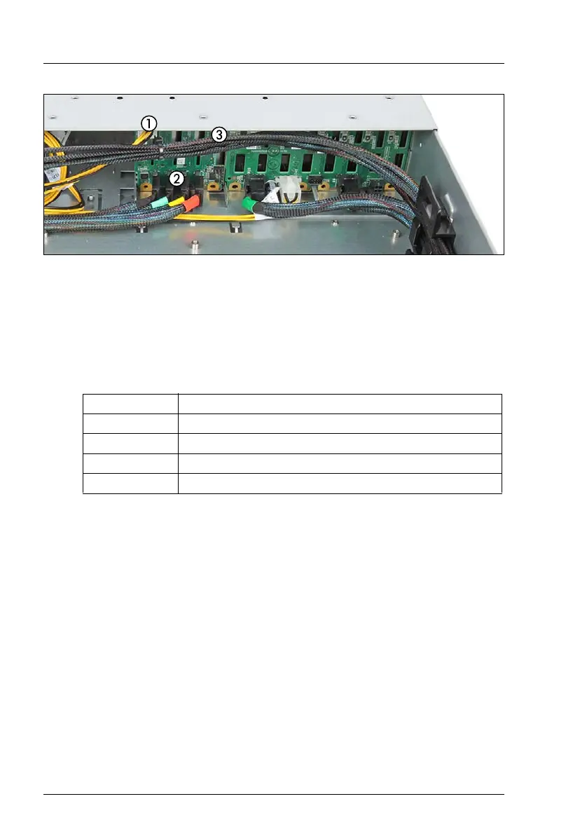
Figure 122: Connecting cables to the 2.5-inch PCIe SSD backplane
Ê Connect the following cables:
– The power cable (1) from the PCIe SSD backplane to the system board
connector "PWR2" (for the first PCIe SSD backplane) or "PWR3" (for the
second PCIe SSD backplane).
– The color-coded Oculink cables (2) to the PCIe SSD backplane:
– If applicable, the OOB cable (3) from the PCIe SSD backplane to the
system board connector "OOB Front".
7.4.12.4 Installing the controller
Ê If applicable, install the controller, see section "Installing an expansion card"
on page 253.
7.4.12.5 Installing additional PCIe SSD modules
Ê Remove the dummy locks, see section "Removing a 2.5-inch dummy
module" on page 182.
Ê Insert additional PCIe SSDs, see section "Installing a 2.5-inch HDD/SSD
module" on page 183.
Color Connector on PCIe SSD backplane
red "P0_X1"
yellow "P1_X2"
green "P2_X3"
black "P3_X4"

 Loading...


