RX2540 M4 Upgrade and Maintenance Manual 437
14 Front panel
Safety notes
V CAUTION!
● When inserting the front panel module into the server, ensure not to
pinch or strain any connected cables.
● Circuit boards and soldered parts of internal options are exposed and
can be damaged by static electricity. Always discharge static build-up
(e.g. by touching a grounded object) before handling electrostatic-
sensitive devices (ESDs).
● Do not touch the circuitry on boards or soldered parts. Hold circuit
boards by their metallic areas or edges.
● For more information, see chapter "Important information" on
page 41.
14.1 Basic information
In case of a defective ambient temperature sensor, please replace the front
panel.
Front panel module
The front panel module consists of a holder and a front panel board. These
components are already pre-assembled. The USB connector of the front USB
cable must be installed in the dependant recesses of the holder. As an option
the holder can be equipped with a front VGA connector.
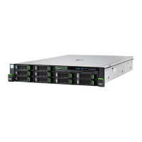
Front panel on QRL (10 x 2.5-inch HDD configuration)
The front panel on QRL (Quick Release Lever) is only available for the servers
with a 10 x 2.5-inch HDD configuration. The front panel is mounted on the right
side ear. A flat cable is used for connection to the system board.
 Loading...
