RX2540 M4 Upgrade and Maintenance Manual 371
Ê Lift up the slot bracket with the tubes (2) and pull it in the direction of the
arrow (3).
Ê Disconnect the two control cables from the system board, see figure 242 on
page 364.
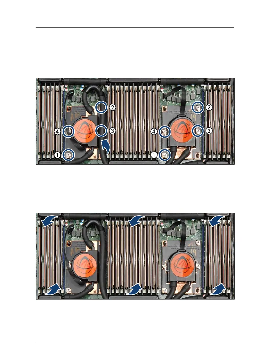
Figure 251: Removing the captive screws of the CPUs
Ê Pull up the tube (see arrow) to get access to the screws 2 and 3.
Ê Remove the four captive screws for CPU 1 in a crossover pattern (4 to 1).
Ê Remove the four captive screws for CPU 2 in a crossover pattern (4 to 1).
Figure 252: Removing the LC device
Ê Carefully lift up the three memory cooling units (see arrows).

 Loading...


