RM0090 Power controller (PWR)
Doc ID 018909 Rev 4 106/1422
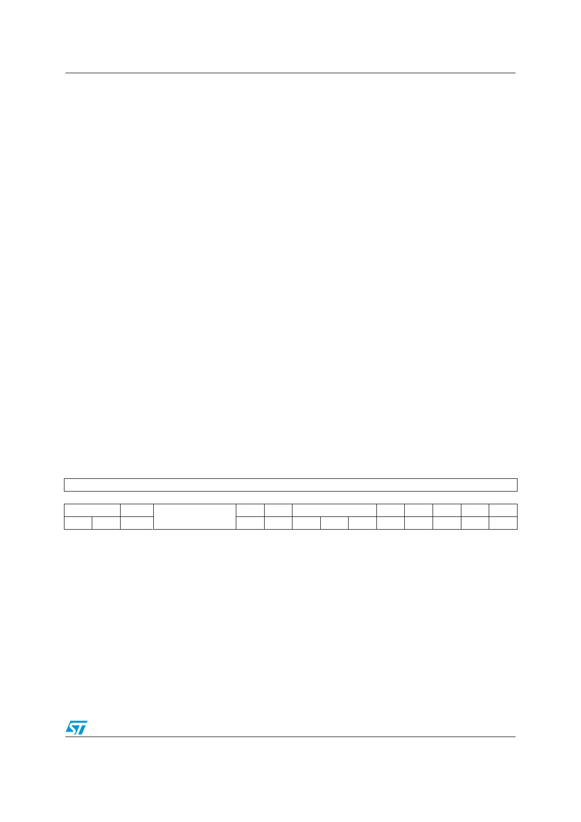
5.4.2 PWR power control register (PWR_CR)
for STM32F42xxx and STM32F43xxx
Address offset: 0x00
Reset value: 0x0000 C000 (reset by wakeup from Standby mode)
Bit 4 PVDE: Power voltage detector enable
This bit is set and cleared by software.
0: PVD disabled
1: PVD enabled
Bit 3 CSBF: Clear standby flag
This bit is always read as 0.
0: No effect
1: Clear the SBF Standby Flag (write).
Bit 2 CWUF: Clear wakeup flag
This bit is always read as 0.
0: No effect
1: Clear the WUF Wakeup Flag after 2 System clock cycles
Bit 1 PDDS: Power-down deepsleep
This bit is set and cleared by software. It works together with the LPDS bit.
0: Enter Stop mode when the CPU enters deepsleep. The regulator status depends on the
LPDS bit.
1: Enter Standby mode when the CPU enters deepsleep.
Bit 0 LPDS: Low-power deepsleep
This bit is set and cleared by software. It works together with the PDDS bit.
0: Voltage regulator on during Stop mode
1: Voltage regulator in low-power mode during Stop mode
31 30 29 28 27 26 25 24 23 22 21 20 19 18 17 16
Reserved
1514131211109876543210
VOS ADCDC1
Reserved
FPDS DBP PLS[2:0] PVDE CSBF CWUF PDDS LPDS
rw rw rw rw rw rw rw rw rw rc_w1 rc_w1 rw rw

 Loading...


