General-purpose timers (TIM9 to TIM14) RM0090
491/1422 Doc ID 018909 Rev 4
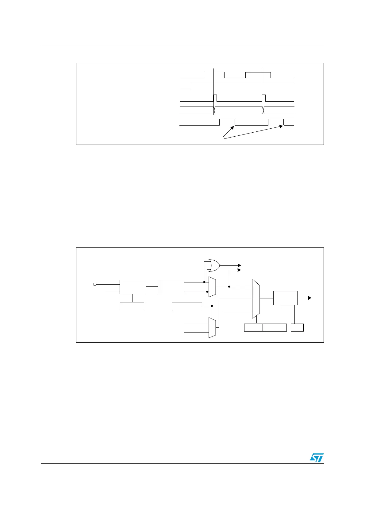
Figure 177. Control circuit in external clock mode 1
16.4.4 Capture/compare channels
Each Capture/Compare channel is built around a capture/compare register (including a
shadow register), a input stage for capture (with digital filter, multiplexing and prescaler) and
an output stage (with comparator and output control).
Figure 178 to Figure 180 give an overview of one capture/compare channel.
The input stage samples the corresponding TIx input to generate a filtered signal TIxF.
Then, an edge detector with polarity selection generates a signal (TIxFPx) which can be
used as trigger input by the slave mode controller or as the capture command. It is
prescaled before the capture register (ICxPS).
Figure 178. Capture/compare channel (example: channel 1 input stage)
The output stage generates an intermediate waveform which is then used for reference:
OCxRef (active high). The polarity acts at the end of the chain.
Counter clock = CK_CNT = CK_PSC
Counter register
35 3634
TI2
CNT_EN
TIF
Write TIF=0
TI1
0
1
TIMx_CCER
CC1P/CC1NP
divider
/1, /2, /4, /8
ICPS[1:0]
TI1F_ED
filter
ICF[3:0]
downcounter
TIMx_CCMR1
Edge
Detector
TI1F_Rising
TI1F_Falling
to the slave mode controller
TI1FP1
11
01
TIMx_CCMR1
CC1S[1:0]
IC1
TI2FP1
TRC
(from channel 2)
(from slave mode
controller)
10
f
DTS
TIMx_CCER
CC1E
IC1PS
TI1F
0
1
TI2F_rising
TI2F_falling
(from channel 2)

 Loading...


