General-purpose timers (TIM9 to TIM14) RM0090
489/1422 Doc ID 018909 Rev 4
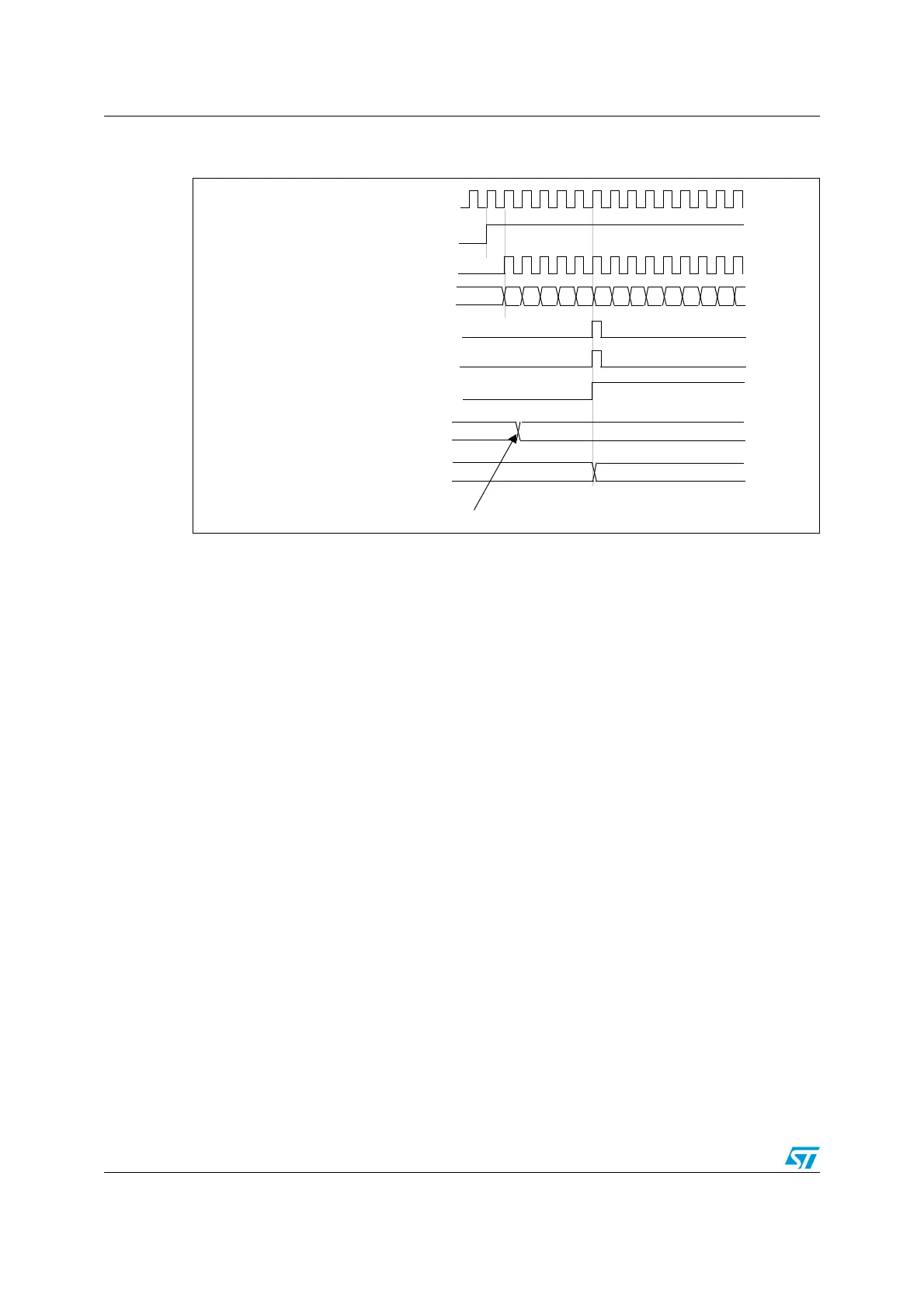
Figure 174. Counter timing diagram, update event when ARPE=1 (TIMx_ARR
preloaded)
16.4.3 Clock selection
The counter clock can be provided by the following clock sources:
● Internal clock (CK_INT)
● External clock mode1 (for TIM9 and TIM12): external input pin (TIx)
● Internal trigger inputs (ITRx) (for TIM9 and TIM12): connecting the trigger output from
another timer. Refer to Section : Using one timer as prescaler for another for more
details.
Internal clock source (CK_INT)
The internal clock source is the default clock source for TIM10/TIM11 and TIM13/TIM14.
For TIM9 and TIM12, the internal clock source is selected when the slave mode controller is
disabled (SMS=’000’). The CEN bit in the TIMx_CR1 register and the UG bit in the
TIMx_EGR register are then used as control bits and can be changed only by software
(except for UG which remains cleared). As soon as the CEN bit is programmed to 1, the
prescaler is clocked by the internal clock CK_INT.
Figure 175 shows the behavior of the control circuit and the upcounter in normal mode,
without prescaler.
CK_PSC
00
CEN
Timer clock = CK_CNT
Counter register
Update interrupt flag (UIF)
Counter overflow
Update event (UEV)
01 02 03 04 05 06 07F1 F2 F3 F4 F5F0
Auto-reload preload register
F5 36
Auto-reload shadow register
F5 36
Write a new value in TIMx_ARR

 Loading...


