Serial peripheral interface (SPI) RM0090
823/1422 Doc ID 018909 Rev 4
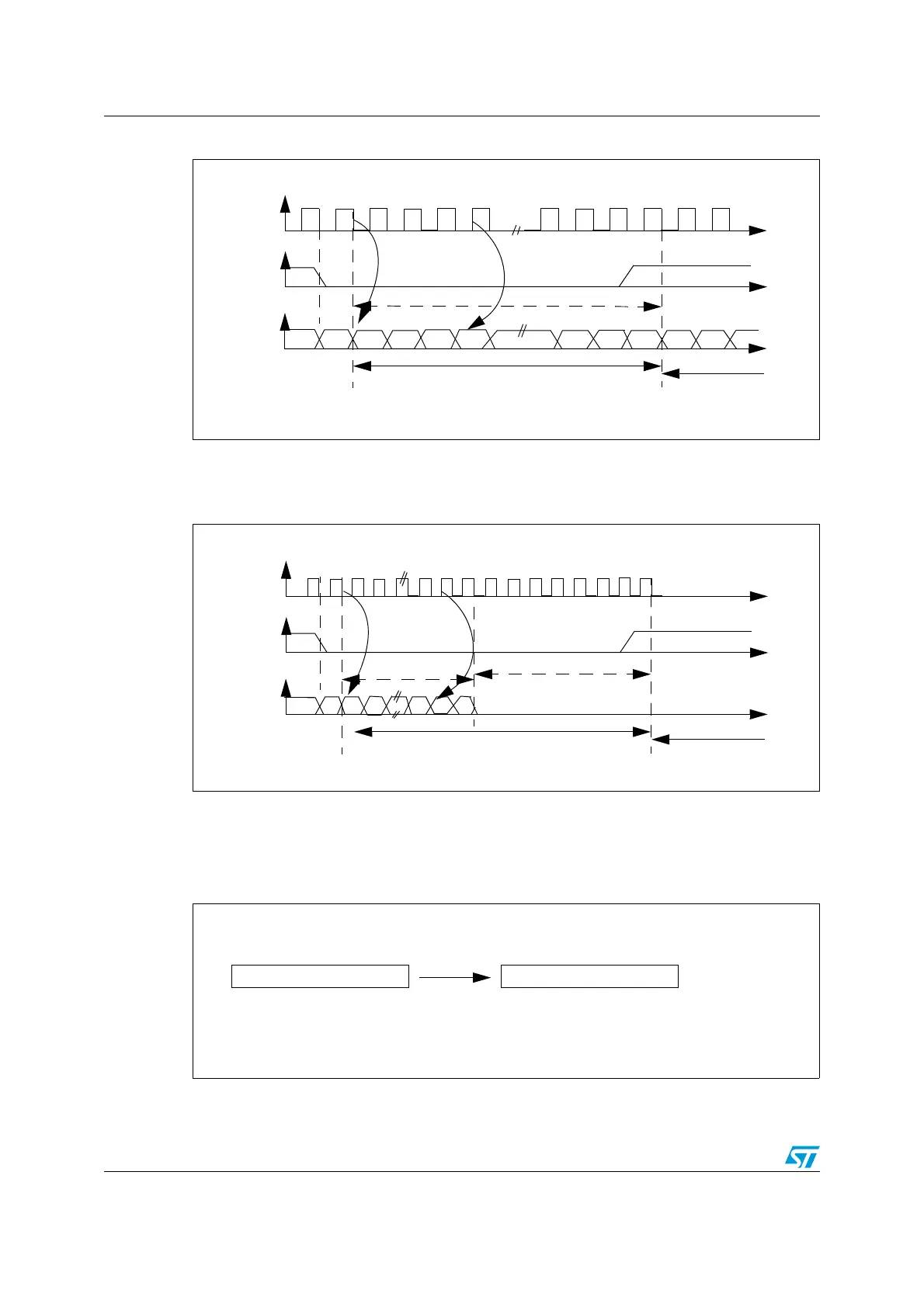
Figure 289. I
2
S Philips protocol waveforms (16/32-bit full accuracy, CPOL = 0)
Data are latched on the falling edge of CK (for the transmitter) and are read on the rising
edge (for the receiver). The WS signal is also latched on the falling edge of CK.
Figure 290. I
2
S Philips standard waveforms (24-bit frame with CPOL = 0)
This mode needs two write or read operations to/from the SPI_DR.
● In transmission mode:
if 0x8EAA33 has to be sent (24-bit):
Figure 291. Transmitting 0x8EAA33
MSB
LSB
MSB
CK
WS
SD
Channel left
Channel right
May be 16-bit, 32-bit
Transmission
Reception
CK
WS
SD
Channel left 32-bit
Channel right
MSB LSB
8-bit remaining
0 forced
24-bit data
Transmission
Reception
0x8EAA 0x33XX
Only the 8 MSBs are sent to complete the 24 bits
First write to Data register
Second write to Data register
8 LSB bits have no meaning and could be
anything

 Loading...


