RM0090 Secure digital input/output interface (SDIO)
Doc ID 018909 Rev 4 884/1422
28.5.8 R6
Only for SD I/O. The normal response to CMD3 by a memory device. It is shown in
Table 157.
The card [23:8] status bits are changed when CMD3 is sent to an I/O-only card. In this case,
the 16 bits of response are the SD I/O-only values:
● Bit [15] COM_CRC_ERROR
● Bit [14] ILLEGAL_COMMAND
● Bit [13] ERROR
● Bits [12:0] Reserved
28.6 SDIO I/O card-specific operations
The following features are SD I/O-specific operations:
● SDIO read wait operation by SDIO_D2 signalling
● SDIO read wait operation by stopping the clock
● SDIO suspend/resume operation (write and read suspend)
● SDIO interrupts
The SDIO supports these operations only if the SDIO_DCTRL[11] bit is set, except for read
suspend that does not need specific hardware implementation.
28.6.1 SDIO I/O read wait operation by SDIO_D2 signalling
It is possible to start the readwait interval before the first block is received: when the data
path is enabled (SDIO_DCTRL[0] bit set), the SDIO-specific operation is enabled
(SDIO_DCTRL[11] bit set), read wait starts (SDI0_DCTRL[10] =0 and SDI_DCTRL[8] =1)
and data direction is from card to SDIO (SDIO_DCTRL[1] = 1), the DPSM directly moves
from Idle to Readwait. In Readwait the DPSM drives SDIO_D2 to 0 after 2 SDIO_CK clock
cycles. In this state, when you set the RWSTOP bit (SDIO_DCTRL[9]), the DPSM remains
in Wait for two more SDIO_CK clock cycles to drive SDIO_D2 to 1 for one clock cycle (in
accordance with SDIO specification). The DPSM then starts waiting again until it receives
data from the card. The DPSM will not start a readwait interval while receiving a block even
if read wait start is set: the readwait interval will start after the CRC is received. The
RWSTOP bit has to be cleared to start a new read wait operation. During the readwait
interval, the SDIO can detect SDIO interrupts on SDIO_D1.
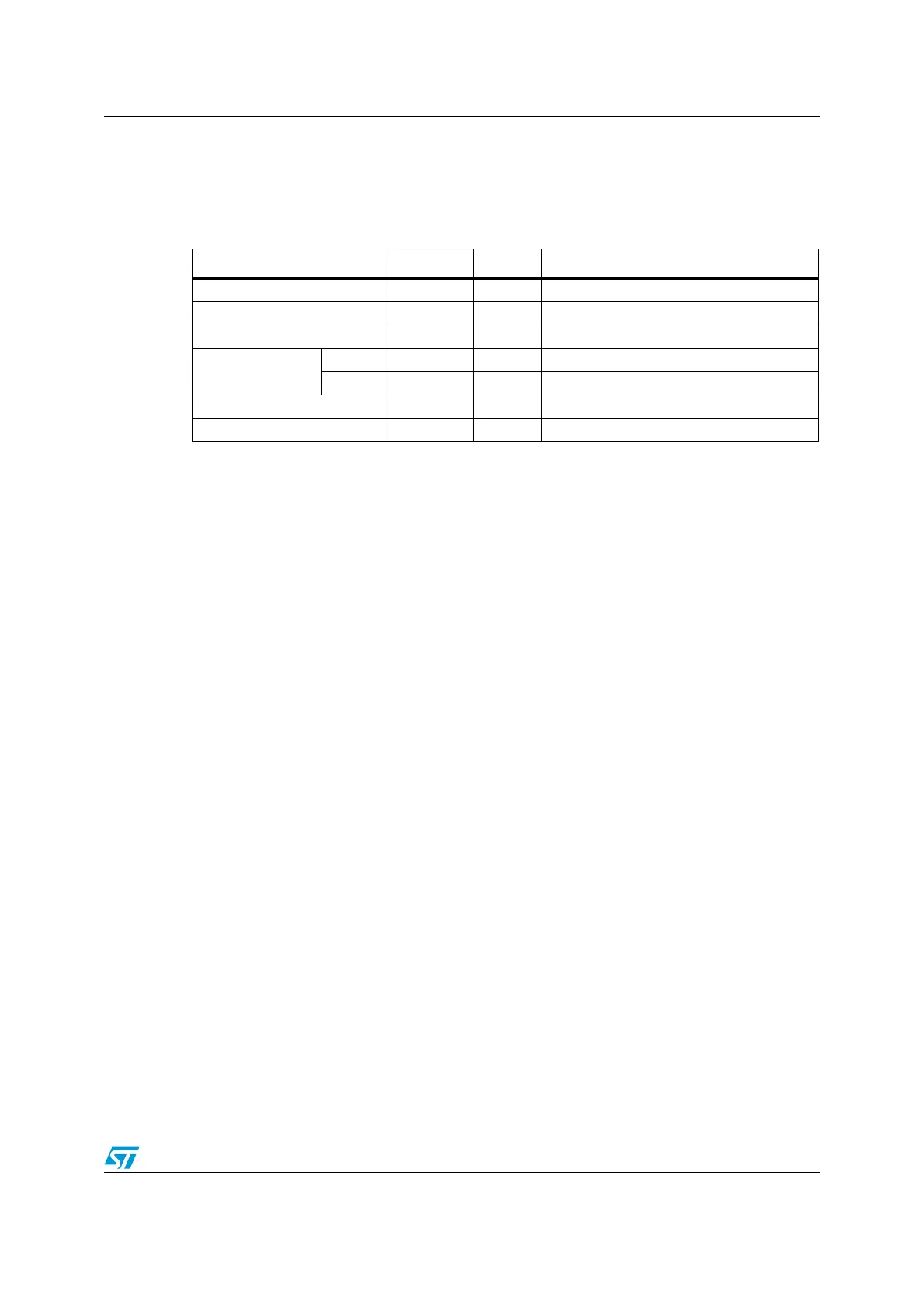
Table 157. R6 response
Bit position Width (bits) Value Description
47 1 0 Start bit
46 1 0 Transmission bit
[45:40] 6 ‘101000’ CMD40
[39:8] Argument
field
[31:16] 16 X RCA [31:16] of winning card or of the host
[15:0] 16 X Not defined. May be used for IRQ data
[7:1] 7 X CRC7
0 1 1 End bit

 Loading...


