Reset and clock control for (RCC) RM0090
121/1422 Doc ID 018909 Rev 4
with the same resolution, and trim the source to compensate for manufacturing-process
and/or temperature- and voltage-related frequency deviations.
The HSI oscillator has dedicated, user-accessible calibration bits for this purpose.
The basic concept consists in providing a relative measurement (e.g. HSI/LSE ratio): the
precision is therefore tightly linked to the ratio between the two clock sources. The greater
the ratio, the better the measurement.
It is also possible to measure the LSI frequency: this is useful for applications that do not
have a crystal. The ultralow-power LSI oscillator has a large manufacturing process
deviation: by measuring it versus the HSI clock source, it is possible to determine its
frequency with the precision of the HSI. The measured value can be used to have more
accurate RTC time base timeouts (when LSI is used as the RTC clock source) and/or an
IWDG timeout with an acceptable accuracy.
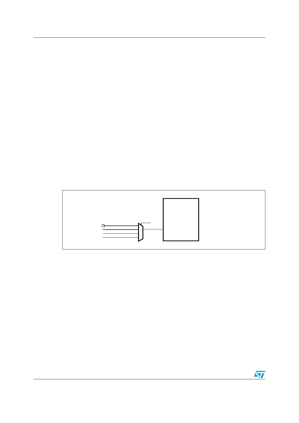
Use the following procedure to measure the LSI frequency:
1. Enable the TIM5 timer and configure channel4 in Input capture mode.
2. Set the TI4_RMP bits in the TIM5_OR register to 0x01 to connect the LSI clock
internally to TIM5 channel4 input capture for calibration purposes.
3. Measure the LSI clock frequency using the TIM5 capture/compare 4 event or interrupt.
4. Use the measured LSI frequency to update the prescaler of the RTC depending on the
desired time base and/or to compute the IWDG timeout.
Figure 15. Frequency measurement with TIM5 in Input capture mode
Internal/external clock measurement using TIM11 channel1
TIM11 has an input multiplexer which allows choosing whether the input capture is triggered
by the I/O or by an internal clock. This selection is performed through TI1_RMP [1:0] bits in
the TIM11_OR register. The HSE_RTC clock (HSE divided by a programmable prescaler) is
connected to channel 1 input capture to have a rough indication of the external crystal
frequency. This requires that the HSI is the system clock source. This can be useful for
instance to ensure compliance with the IEC 60730/IEC 61335 standards which require to be
able to determine harmonic or subharmonic frequencies (–50/+100% deviations).
TIM5
TI4
TI4_RMP[1:0]
GPIO
RTC_WakeUp_IT
LSE
LSI
ai17741V2

 Loading...


