General-purpose timers (TIM2 to TIM5) RM0090
455/1422 Doc ID 018909 Rev 4
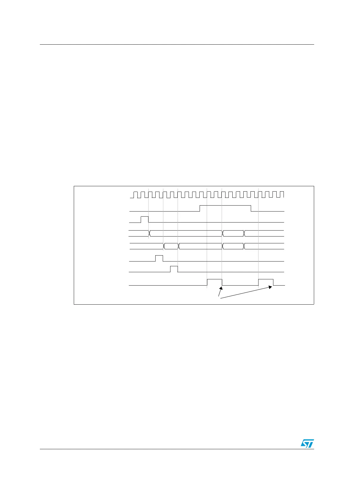
timers. Timer 2 stops when Timer 1 is disabled by writing ‘0 to the CEN bit in the TIM1_CR1
register:
● Configure Timer 1 master mode to send its Output Compare 1 Reference (OC1REF)
signal as trigger output (MMS=100 in the TIM1_CR2 register).
● Configure the Timer 1 OC1REF waveform (TIM1_CCMR1 register).
● Configure Timer 2 to get the input trigger from Timer 1 (TS=000 in the TIM2_SMCR
register).
● Configure Timer 2 in gated mode (SMS=101 in TIM2_SMCR register).
● Reset Timer 1 by writing ‘1 in UG bit (TIM1_EGR register).
● Reset Timer 2 by writing ‘1 in UG bit (TIM2_EGR register).
● Initialize Timer 2 to 0xE7 by writing ‘0xE7’ in the timer 2 counter (TIM2_CNTL).
● Enable Timer 2 by writing ‘1 in the CEN bit (TIM2_CR1 register).
● Start Timer 1 by writing ‘1 in the CEN bit (TIM1_CR1 register).
● Stop Timer 1 by writing ‘0 in the CEN bit (TIM1_CR1 register).
Figure 161. Gating timer 2 with Enable of timer 1
Using one timer to start another timer
In this example, we set the enable of Timer 2 with the update event of Timer 1. Refer to
Figure 159 for connections. Timer 2 starts counting from its current value (which can be
nonzero) on the divided internal clock as soon as the update event is generated by Timer 1.
When Timer 2 receives the trigger signal its CEN bit is automatically set and the counter
counts until we write ‘0 to the CEN bit in the TIM2_CR1 register. Both counter clock
frequencies are divided by 3 by the prescaler compared to CK_INT (f
CK_CNT
= f
CK_INT
/3).
● Configure Timer 1 master mode to send its Update Event (UEV) as trigger output
(MMS=010 in the TIM1_CR2 register).
● Configure the Timer 1 period (TIM1_ARR registers).
● Configure Timer 2 to get the input trigger from Timer 1 (TS=000 in the TIM2_SMCR
register).
● Configure Timer 2 in trigger mode (SMS=110 in TIM2_SMCR register).
● Start Timer 1 by writing ‘1 in the CEN bit (TIM1_CR1 register).
TIMER 2-TIF
Write TIF=0
75 00 01
CK_INT
TIMER1-CEN=CNT_EN
TIMER1-CNT
TIMER2-CNT
02
TIMER1-CNT_INIT
AB 00 E7 E8 E9
TIMER2-CNT_INIT
TIMER2
write CNT

 Loading...


