RM0090 General-purpose timers (TIM2 to TIM5)
Doc ID 018909 Rev 4 452/1422
1. Configure the external trigger input circuit by programming the TIMx_SMCR register as
follows:
– ETF = 0000: no filter
– ETPS = 00: prescaler disabled
– ETP = 0: detection of rising edges on ETR and ECE=1 to enable the external clock
mode 2.
2. Configure the channel 1 as follows, to detect rising edges on TI:
– IC1F = 0000: no filter.
– The capture prescaler is not used for triggering and does not need to be
configured.
– CC1S = 01 in TIMx_CCMR1 register to select only the input capture source
– CC1P = 0 in TIMx_CCER register to validate the polarity (and detect rising edge
only).
3. Configure the timer in trigger mode by writing SMS=110 in TIMx_SMCR register. Select
TI1 as the input source by writing TS=101 in TIMx_SMCR register.
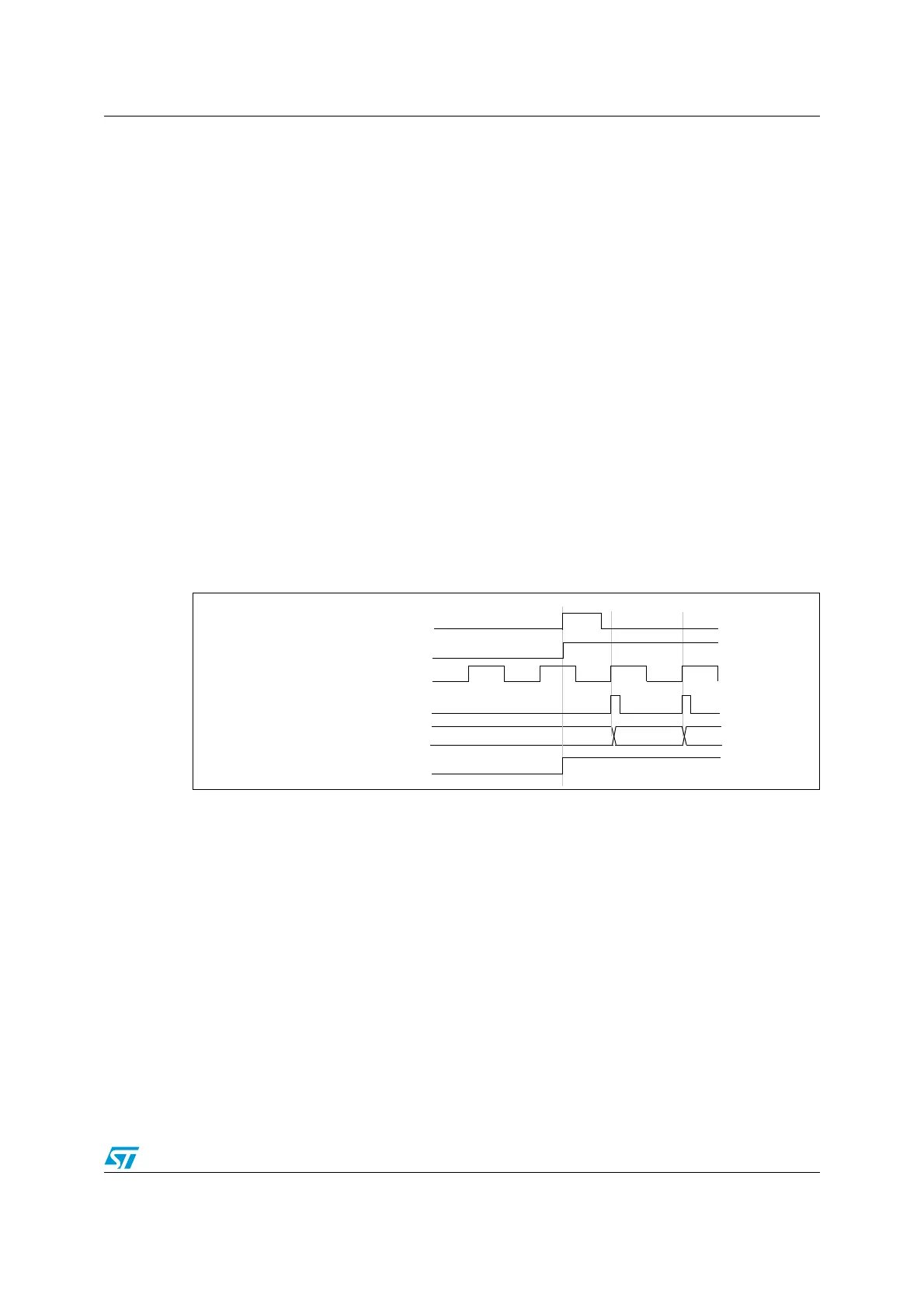
A rising edge on TI1 enables the counter and sets the TIF flag. The counter then counts on
ETR rising edges.
The delay between the rising edge of the ETR signal and the actual reset of the counter is
due to the resynchronization circuit on ETRP input.
Figure 158. Control circuit in external clock mode 2 + trigger mode
Counter clock = CK_CNT = CK_PSC
Counter register
35 3634
ETR
CEN/CNT_EN
TIF
TI1

 Loading...


