RM0090 Digital camera interface (DCMI)
Doc ID 018909 Rev 4 334/1422
word. The remaining most significant bits are cleared to zero. So, in this case a 32-bit data
word is made up every two pixel clock cycles.
The first captured data are placed in the LSB position in the 32-bit word and the 2
nd
captured data are placed in the MSB position in the 32-bit word as shown in Ta bl e 6 5 .
13.5.3 Synchronization
The digital camera interface supports embedded or hardware (HSYNC & VSYNC)
synchronization. When embedded synchronization is used, it is up to the digital camera
module to make sure that the 0x00 and 0xFF values are used ONLY for synchronization (not
in data). Embedded synchronization codes are supported only for the 8-bit parallel data
interface width (that is, in the DCMI_CR register, the EDM[1:0] bits should be cleared to
“00”).
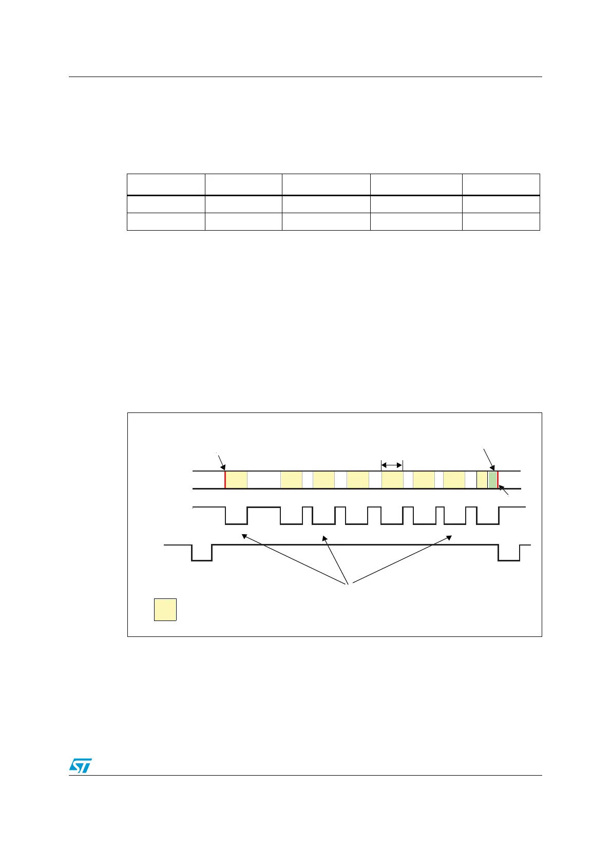
For compressed data, the DCMI supports only the hardware synchronization mode. In this
case, VSYNC is used as a start/end of the image, and HSYNC is used as a Data Valid
signal. Figure 65 shows the corresponding timing diagram.
Figure 65. Timing diagram
Table 65. Positioning of captured data bytes in 32-bit words (14-bit width)
Byte address 31:30 29:16 15:14 13:0
00D
n+1
[13:0] 0 D
n
[13:0]
40D
n+3
[13:0] 0 D
n+2
[13:0]
Padding data at the
end of the JPEG stream
JPEG packet size
programmable
End of JPEG stream
Beginning of JPEG stream
JPEG data
HSYNC
VSYNC
Packet dispatching depends on the image content.
This results in a variable blanking duration.
JPEG packet data
ai15944

 Loading...


