RM0090 Ethernet (ETH): media access control (MAC) with DMA controller
Doc ID 018909 Rev 4 908/1422
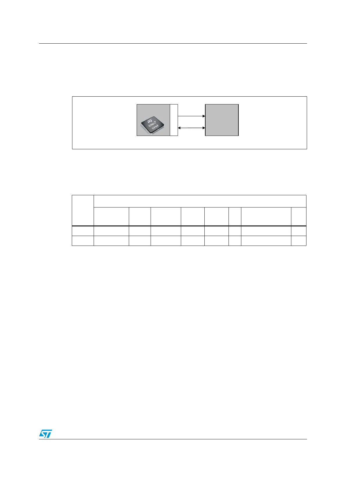
160 ns each, and the minimum period for MDC must be 400 ns. In idle state the SMI
management interface drives the MDC clock signal low.
● MDIO: data input/output bitstream to transfer status information to/from the PHY device
synchronously with the MDC clock signal
Figure 322. SMI interface signals
SMI frame format
The frame structure related to a read or write operation is shown in Ta b l e 1 3 , the order of bit
transmission must be from left to right.
The management frame consists of eight fields:
● Preamble: each transaction (read or write) can be initiated with the preamble field that
corresponds to 32 contiguous logic one bits on the MDIO line with 32 corresponding
cycles on MDC. This field is used to establish synchronization with the PHY device.
● Start: the start of frame is defined by a <01> pattern to verify transitions on the line
from the default logic one state to zero and back to one.
● Operation: defines the type of transaction (read or write) in progress.
● PADDR: the PHY address is 5 bits, allowing 32 unique PHY addresses. The MSB bit of
the address is the first transmitted and received.
● RADDR: the register address is 5 bits, allowing 32 individual registers to be addressed
within the selected PHY device. The MSB bit of the address is the first transmitted and
received.
● TA: the turn-around field defines a 2-bit pattern between the RADDR and DATA fields to
avoid contention during a read transaction. For a read transaction the MAC controller
drives high-impedance on the MDIO line for the 2 bits of TA. The PHY device must
drive a high-impedance state on the first bit of TA, a zero bit on the second one.
For a write transaction, the MAC controller drives a <10> pattern during the TA field.
The PHY device must drive a high-impedance state for the 2 bits of TA.
● Data: the data field is 16-bit. The first bit transmitted and received must be bit 15 of the
ETH_MIID register.
Table 161. Management frame format
Management frame fields
Preamble
(32 bits)
Start Operation PADDR RADDR TA Data (16 bits) Idle
Read 1... 1 01 10 ppppp rrrrr Z0 ddddddddddddddd Z
Write 1... 1 01 01 ppppp rrrrr 10 ddddddddddddddd Z
STM32
MDIO
MDC
External
PHY
ai15621
802.3 MAC

 Loading...


