RM0090 Real-time clock (RTC)
Doc ID 018909 Rev 4 660/1422
23.6.18 RTC alarm A sub second register (RTC_ALRMASSR)
Address offset: 0x44
Power-on reset value: 0x0000 0000
System reset: not affected
Note: This register can be written only when ALRAE is reset in RTC_CR register, or in initialization
mode.
This register is write protected. The write access procedure is described in RTC register
write protection on page 630
Bit 0 TAMP1E: Tamper 1 detection enable
0: Tamper 1 detection disabled
1: Tamper 1 detection enabled
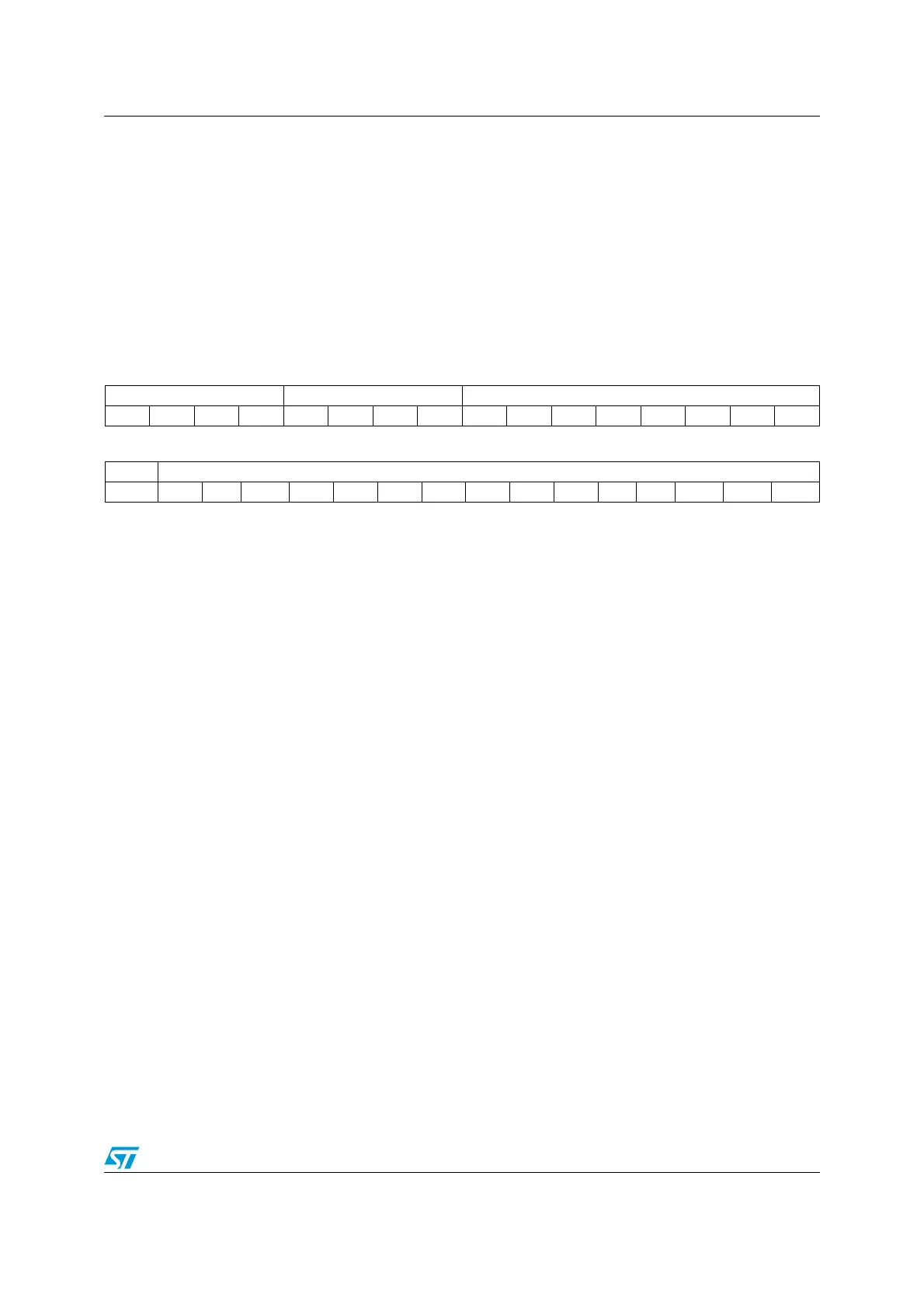
31 30 29 28 27 26 25 24 23 22 21 20 19 18 17 16
Reserved MASKSS[3:0] Reserved
rrrrrwrwrwrwrrrrrrrr
15141312111098765432 1 0
Reserved SS[14:0]
r rwrwrw rwrwrwrwrwrwrwrwrww rw rw
Bit 31:28 Reserved
Bit 27:24 MASKSS[3:0]: Mask the most-significant bits starting at this bit
0: No comparison on sub seconds for Alarm A. The alarm is set when the seconds unit is
incremented (assuming that the rest of the fields match).
1: SS[14:1] are don’t care in Alarm A comparison. Only SS[0] is compared.
2: SS[14:2] are don’t care in Alarm A comparison. Only SS[1:0] are compared.
3: SS[14:3] are don’t care in Alarm A comparison. Only SS[2:0] are compared.
...
12: SS[14:12] are don’t care in Alarm A comparison. SS[11:0] are compared.
13: SS[14:13] are don’t care in Alarm A comparison. SS[12:0] are compared.
14: SS[14] is don’t care in Alarm A comparison. SS[13:0] are compared.
15: All 15 SS bits are compared and must match to activate alarm.
The overflow bits of the synchronous counter (bits 15) is never compared. This bit can be
different from 0 only after a shift operation.
Bit 23:15 Reserved
Bit 14:0 SS[14:0]: Sub seconds value
This value is compared with the contents of the synchronous prescaler’s counter to
determine if Alarm A is to be activated. Only bits 0 up MASKSS-1 are compared.

 Loading...


