DMA controller (DMA) RM0090
217/1422 Doc ID 018909 Rev 4
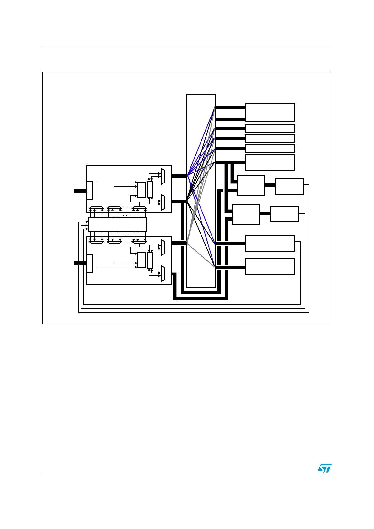
Figure 26. System implementation of the two DMA controllers (STM32F42xxx and
STM32F43xxx)
1. The DMA1 controller AHB peripheral port is not connected to the bus matrix like in the case of the DMA2 controller, thus
only DMA2 streams are able to perform memory-to-memory transfers.
9.3.2 DMA transactions
A DMA transaction consists of a sequence of a given number of data transfers. The number
of data items to be transferred and their width (8-bit, 16-bit or 32-bit) are software-
programmable.
Each DMA transfer consists of three operations:
● A loading from the peripheral data register or a location in memory, addressed through
the DMA_SxPAR or DMA_SxM0AR register
● A storage of the data loaded to the peripheral data register or a location in memory
addressed through the DMA_SxPAR or DMA_SxM0AR register
● A post-decrement of the DMA_SxNDTR register, which contains the number of
transactions that still have to be performed
MS30437V1
DMA controller 1
AHB periph
Arbiter
AHB memory
FIFO
DMA controller 2
AHB memory
Bus Matrix
(AHB multilayer)
Arbiter
AHB periph
MAPPING
FIFO
External memory
Flash
memory
112 KB SRAM
AHB2 peripherals
AHB-APB
bridge2
(dual AHB)
APB2
APB2
AHB-APB
bridge1
(dual AHB)
APB1
APB1
peripherals
AHB slave
AHB slave
portportportport
controller (FSMC)
DMA request
peripherals
16 KB SRAM
AHB1 peripherals
To AHB2
peripherals
To AHB2
peripherals
DCODE
ICODE
64 KB SRAM

 Loading...


