RM0090 Digital-to-analog converter (DAC)
Doc ID 018909 Rev 4 314/1422
12.3.5 DAC output voltage
Digital inputs are converted to output voltages on a linear conversion between 0 and V
REF+
.
The analog output voltages on each DAC channel pin are determined by the following
equation:
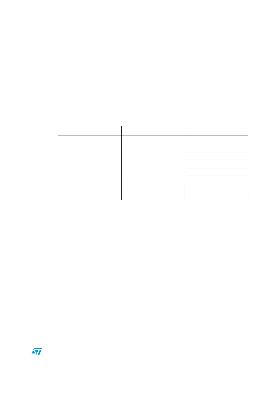
12.3.6 DAC trigger selection
If the TENx control bit is set, conversion can then be triggered by an external event (timer
counter, external interrupt line). The TSELx[2:0] control bits determine which out of 8 possi-
ble events will trigger conversion as shown in Table 58.
Each time a DAC interface detects a rising edge on the selected timer TRGO output, or on
the selected external interrupt line 9, the last data stored into the DAC_DHRx register are
transferred into the DAC_DORx register. The DAC_DORx register is updated three APB1
cycles after the trigger occurs.
If the software trigger is selected, the conversion starts once the SWTRIG bit is set.
SWTRIG is reset by hardware once the DAC_DORx register has been loaded with the
DAC_DHRx register contents.
Note: TSELx[2:0] bit cannot be changed when the ENx bit is set.
When software trigger is selected, the transfer from the DAC_DHRx register to the
DAC_DORx register takes only one APB1 clock cycle.
12.3.7 DMA request
Each DAC channel has a DMA capability. Two DMA channels are used to service DAC
channel DMA requests.
A DAC DMA request is generated when an external trigger (but not a software trigger)
occurs while the DMAENx bit is set. The value of the DAC_DHRx register is then transferred
into the DAC_DORx register.
In dual mode, if both DMAENx bits are set, two DMA requests are generated. If only one
DMA request is needed, you should set only the corresponding DMAENx bit. In this way, the
application can manage both DAC channels in dual mode by using one DMA request and a
unique DMA channel.
DACoutput V
REF
DOR
4095
--------------
×=
Table 58. External triggers
Source Type TSEL[2:0]
Timer 6 TRGO event
Internal signal from on-chip
timers
000
Timer 8 TRGO event 001
Timer 7 TRGO event 010
Timer 5 TRGO event 011
Timer 2 TRGO event 100
Timer 4 TRGO event 101
EXTI line9 External pin 110
SWTRIG Software control bit 111

 Loading...


