RM0090 Independent watchdog (IWDG)
Doc ID 018909 Rev 4 540/1422
18.4.4 Status register (IWDG_SR)
Address offset: 0x0C
Reset value: 0x0000 0000 (not reset by Standby mode)
Note: If several reload values or prescaler values are used by application, it is mandatory to wait
until RVU bit is reset before changing the reload value and to wait until PVU bit is reset
before changing the prescaler value. However, after updating the prescaler and/or the
reload value it is not necessary to wait until RVU or PVU is reset before continuing code
execution (even in case of low-power mode entry, the write operation is taken into account
and will complete)
18.4.5 IWDG register map
The following table gives the IWDG register map and reset values.
Refer to Table 2 on page 52 for the register boundary addresses.
3130292827262524232221201918171615141312111098765432 1 0
Reserved
RVU PVU
rr
Bits 31:2 Reserved, must be kept at reset value.
Bit 1 RVU: Watchdog counter reload value update
This bit is set by hardware to indicate that an update of the reload value is ongoing. It is reset
by hardware when the reload value update operation is completed in the V
DD
voltage domain
(takes up to 5 RC 40 kHz cycles).
Reload value can be updated only when RVU bit is reset.
Bit 0 PVU: Watchdog prescaler value update
This bit is set by hardware to indicate that an update of the prescaler value is ongoing. It is
reset by hardware when the prescaler update operation is completed in the V
DD
voltage
domain (takes up to 5 RC 40 kHz cycles).
Prescaler value can be updated only when PVU bit is reset.
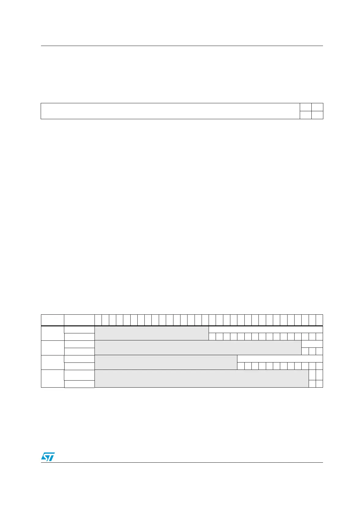
Table 86. IWDG register map and reset values
Offset Register
31
30
29
28
27
26
25
24
23
22
21
20
19
18
17
16
15
14
13
12
11
10
9
8
7
6
5
4
3
2
1
0
0x00
IWDG_KR
Reserved
KEY[15:0]
Reset value 0000000000000000
0x04
IWDG_PR
Reserved
PR[2:0]
Reset value 000
0x08
IWDG_RLR
Reserved
RL[11:0]
Reset value 111111111111
0x0C
IWDG_SR
Reserved
RVU
PVU
Reset value 00

 Loading...


