General-purpose timers (TIM2 to TIM5) RM0090
437/1422 Doc ID 018909 Rev 4
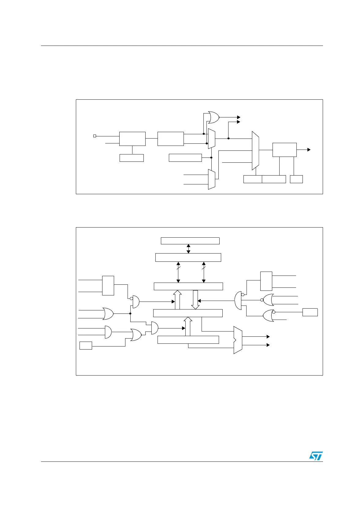
The input stage samples the corresponding TIx input to generate a filtered signal TIxF.
Then, an edge detector with polarity selection generates a signal (TIxFPx) which can be
used as trigger input by the slave mode controller or as the capture command. It is
prescaled before the capture register (ICxPS).
Figure 144. Capture/compare channel (example: channel 1 input stage)
The output stage generates an intermediate waveform which is then used for reference:
OCxRef (active high). The polarity acts at the end of the chain.
Figure 145. Capture/compare channel 1 main circuit
TI1
TIMx_CCER
CC1P/CC1NP
divider
/1, /2, /4, /8
ICPS[1:0]
TI1F_ED
filter
ICF[3:0]
downcounter
TIMx_CCMR1
Edge
Detector
TI1F_Rising
TI1F_Falling
to the slave mode controller
TI1FP1
11
01
TIMx_CCMR1
CC1S[1:0]
IC1
TI2FP1
TRC
(from channel 2)
(from slave mode
controller)
10
f
DTS
TIMx_CCER
CC1E
IC1PS
TI1F
TI2F_rising
TI2F_falling
(from channel 2)
CC1E
Capture/Compare Shadow Register
comparator
Capture/Compare Preload Register
Counter
IC1PS
CC1S[0]
CC1S[1]
capture
input
mode
S
R
read CCR1H
read CCR1L
read_in_progress
capture_transfer
CC1S[0]
CC1S[1]
S
R
write CCR1H
write CCR1L
write_in_progress
output
mode
UEV
OC1PE
(from time
compare_transfer
APB Bus
8
8
high
low
(if 16-bit)
MCU-peripheral interface
TIMx_CCMR1
OC1PE
base unit)
CNT>CCR1
CNT=CCR1
TIMx_EGR
CC1G

 Loading...


