RM0090 Memory and bus architecture
Doc ID 018909 Rev 4 56/1422
A mapping formula shows how to reference each word in the alias region to a corresponding
bit in the bit-band region. The mapping formula is:
bit_word_addr = bit_band_base + (byte_offset x 32) + (bit_number × 4)
where:
– bit_word_addr is the address of the word in the alias memory region that maps to
the targeted bit
– bit_band_base is the starting address of the alias region
– byte_offset is the number of the byte in the bit-band region that contains the
targeted bit
– bit_number is the bit position (0-7) of the targeted bit
Example
The following example shows how to map bit 2 of the byte located at SRAM address
0x20000300 to the alias region:
0x22006008 = 0x22000000 + (0x300*32) + (2*4)
Writing to address 0x22006008 has the same effect as a read-modify-write operation on bit
2 of the byte at SRAM address 0x20000300.
Reading address 0x22006008 returns the value (0x01 or 0x00) of bit 2 of the byte at SRAM
address 0x20000300 (0x01: bit set; 0x00: bit reset).
For more information on bit-banding, please refer to the Cortex™-M4F programming manual
(see Related documents on page 1).
2.4 Boot configuration
Due to its fixed memory map, the code area starts from address 0x0000 0000 (accessed
through the ICode/DCode buses) while the data area (SRAM) starts from address
0x2000 0000 (accessed through the system bus). The Cortex™-M4F CPU always fetches
the reset vector on the ICode bus, which implies to have the boot space available only in the
code area (typically, Flash memory). STM32F4xx microcontrollers implement a special
mechanism to be able to boot from other memories (like the internal SRAM).
In the STM32F4xx, three different boot modes can be selected through the BOOT[1:0] pins
as shown in Tabl e 3 .
The values on the BOOT pins are latched on the 4th rising edge of SYSCLK after a reset. It
is up to the user to set the BOOT1 and BOOT0 pins after reset to select the required boot
mode.
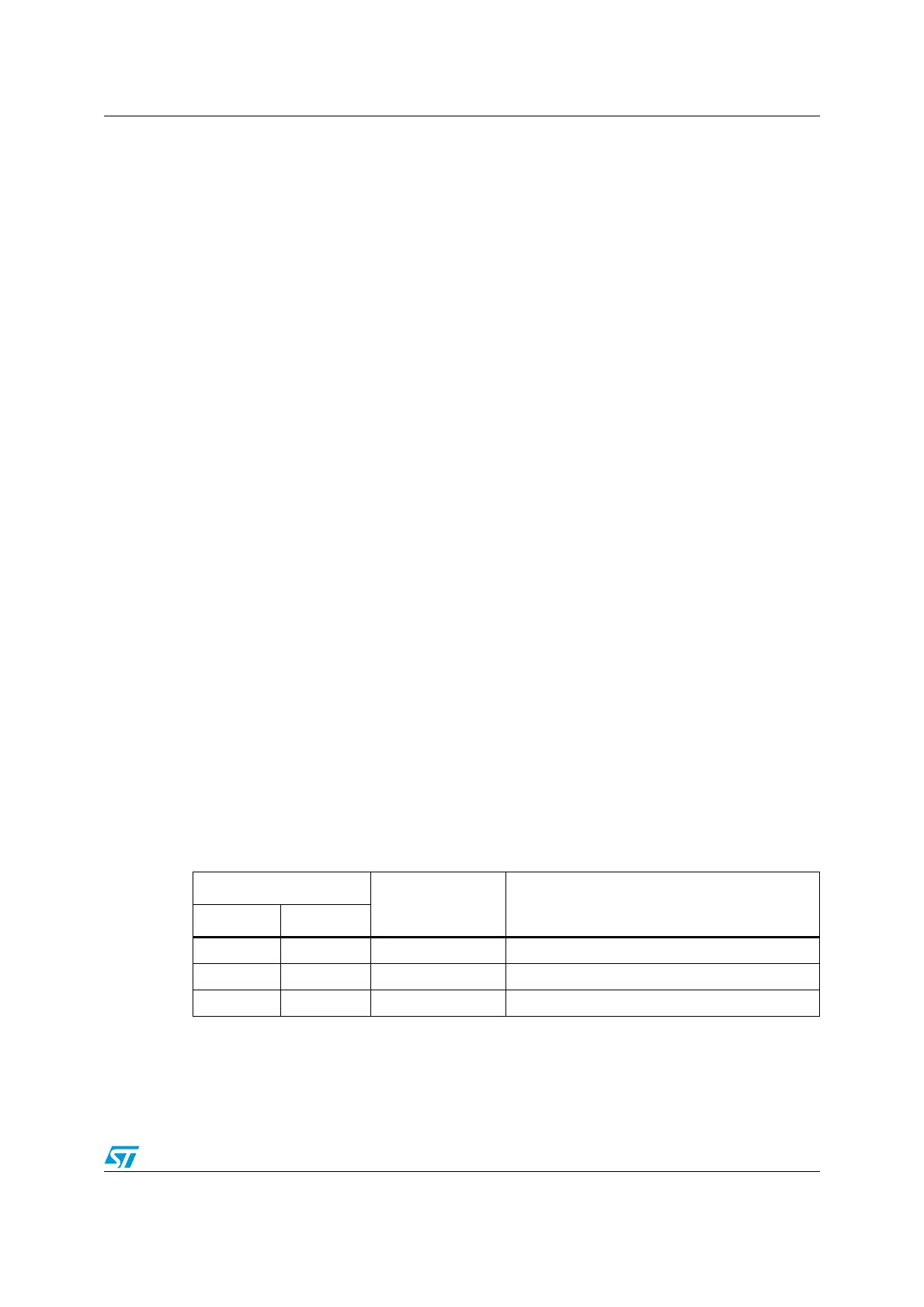
Table 3. Boot modes
Boot mode selection pins
Boot mode Aliasing
BOOT1 BOOT0
x 0 Main Flash memory Main Flash memory is selected as the boot space
0 1 System memory System memory is selected as the boot space
1 1 Embedded SRAM Embedded SRAM is selected as the boot space

 Loading...


