RM0090 Serial peripheral interface (SPI)
Doc ID 018909 Rev 4 836/1422
change. If the synchronization is lost, to recover from this state and resynchronize the
external master device with the I2S slave device, follow the steps below:
1. Disable the I2S
2. Re-enable it when the correct level is detected on the WS line (WS line is high in I2S
mode, or low for MSB- or LSB-justified or PCM modes).
Desynchronization between the master and slave device may be due to noisy environment
on the SCK communication clock or on the WS frame synchronization line. An error interrupt
can be generated if the ERRIE bit is set. The desynchronization flag (FRE) is cleared by
software when the status register is read.
27.4.9 I
2
S interrupts
Table 126 provides the list of I
2
S interrupts.
27.4.10 DMA features
DMA is working in exactly the same way as for the SPI mode. There is no difference on the
I
2
S. Only the CRC feature is not available in I
2
S mode since there is no data transfer
protection system.
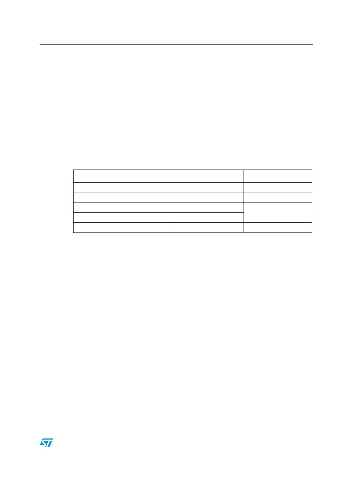
Table 126. I
2
S interrupt requests
Interrupt event Event flag Enable Control bit
Transmit buffer empty flag TXE TXEIE
Receive buffer not empty flag RXNE RXNEIE
Overrun error OVR
ERRIE
Underrun error UDR
Frame error flag FRE ERRIE

 Loading...


