RM0090 Digital camera interface (DCMI)
Doc ID 018909 Rev 4 340/1422
The RGB planar format is compatible with standard OS frame buffer display formats.
Only 16 BPP (bits per pixel): RGB565 (2 pixels per 32-bit word) is supported.
The 24 BPP (palletized format) and grayscale formats are not supported. Pixels are stored
in a raster scan order, that is from top to bottom for pixel rows, and from left to right within a
pixel row. Pixel components are R (red), G (green) and B (blue). All components have the
same spatial resolution (4:4:4 format). A frame is stored in a single part, with the
components interleaved on a pixel basis.
Tabl e 6 7 shows how the data are stored.
13.6.4 YCbCr format
Characteristics:
● Raster format
● YCbCr 4:2:2
● Interleaved: one Buffer: Y, Cb & Cr interleaved: CbYCrYCbYCr, etc.
Pixel components are Y (luminance or “luma”), Cb and Cr (chrominance or “chroma” blue
and red). Each component is encoded in 8 bits. Luma and chroma are stored together
(interleaved) as shown in Tabl e 6 8.
13.7 DCMI interrupts
Five interrupts are generated. All interrupts are maskable by software. The global interrupt
(IT_DCMI) is the OR of all the individual interrupts. Ta b l e 6 9 gives the list of all interrupts.
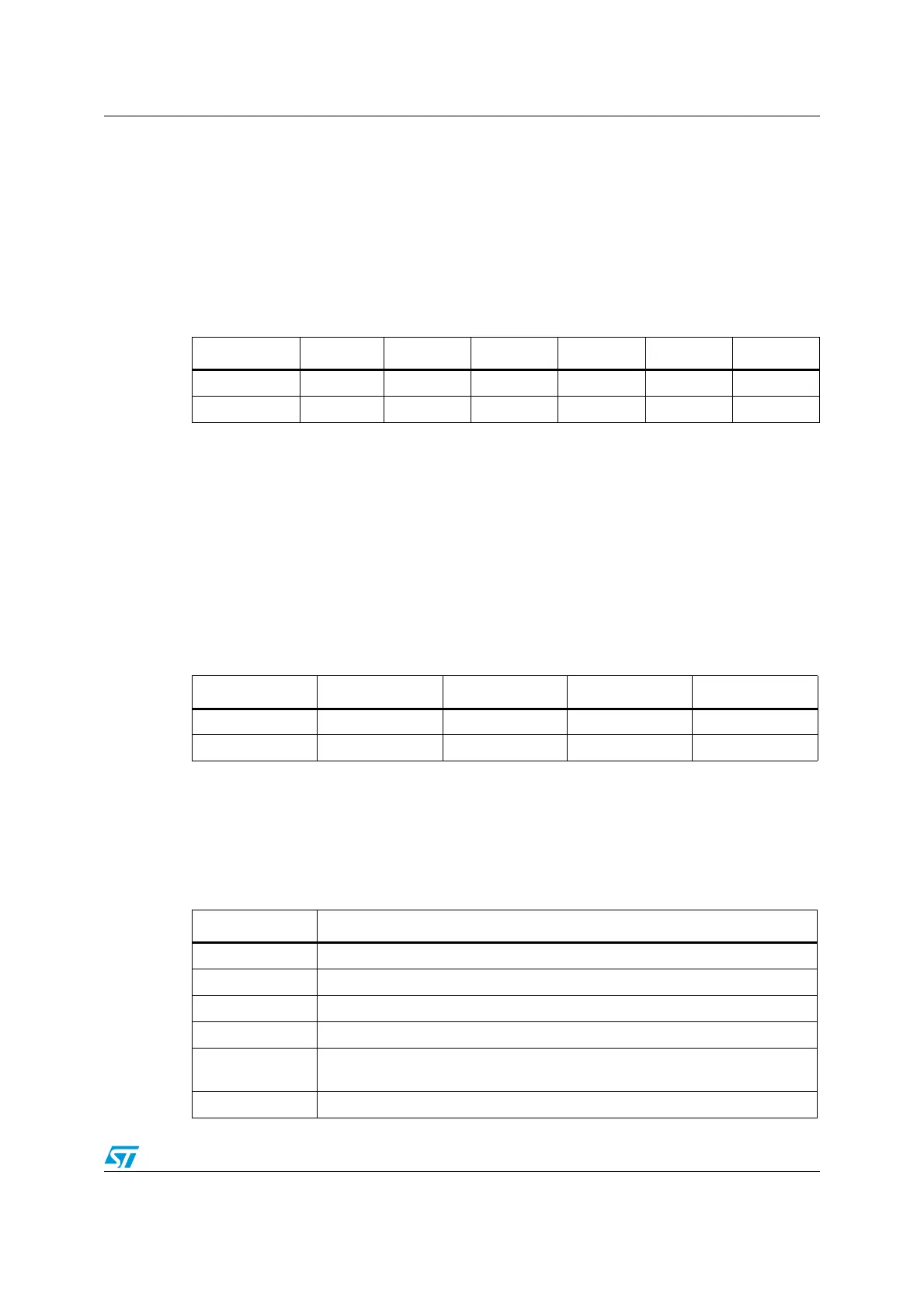
Table 67. Data storage in RGB progressive video format
Byte address 31:27 26:21 20:16 15:11 10:5 4:0
0 Red n + 1 Green n + 1 Blue n + 1 Red n Green n Blue n
4 Red n + 4 Green n + 3 Blue n + 3 Red n + 2 Green n + 2 Blue n + 2
Table 68. Data storage in YCbCr progressive video format
Byte address 31:24 23:16 15:8 7:0
0 Y n + 1 Cr n Y n Cb n
4 Y n + 3 Cr n + 2 Y n + 2 Cb n + 2
Table 69. DCMI interrupts
Interrupt name Interrupt event
IT_LINE Indicates the end of line
IT_FRAME Indicates the end of frame capture
IT_OVR indicates the overrun of data reception
IT_VSYNC Indicates the synchronization frame
IT_ERR
Indicates the detection of an error in the embedded synchronization frame
detection
IT_DCMI Logic OR of the previous interrupts

 Loading...


