Analog-to-digital converter (ADC) RM0090
273/1422 Doc ID 018909 Rev 4
The total conversion time is calculated as follows:
T
conv
= Sampling time + 12 cycles
Example:
With ADCCLK = 30 MHz and sampling time = 3 cycles:
T
conv
= 3 + 12 = 15 cycles = 0.5 µs with APB2 at 60 MHz
11.6 Conversion on external trigger and trigger polarity
Conversion can be triggered by an external event (e.g. timer capture, EXTI line). If the
EXTEN[1:0] control bits (for a regular conversion) or JEXTEN[1:0] bits (for an injected
conversion) are different from “0b00”, then external events are able to trigger a conversion
with the selected polarity. Ta ble 5 0 provides the correspondence between the EXTEN[1:0]
and JEXTEN[1:0] values and the trigger polarity.
Note: The polarity of the external trigger can be changed on the fly.
The EXTSEL[3:0] and JEXTSEL[3:0] control bits are used to select which out of 16 possible
events can trigger conversion for the regular and injected groups.
Tabl e 5 1 gives the possible external trigger for regular conversion.
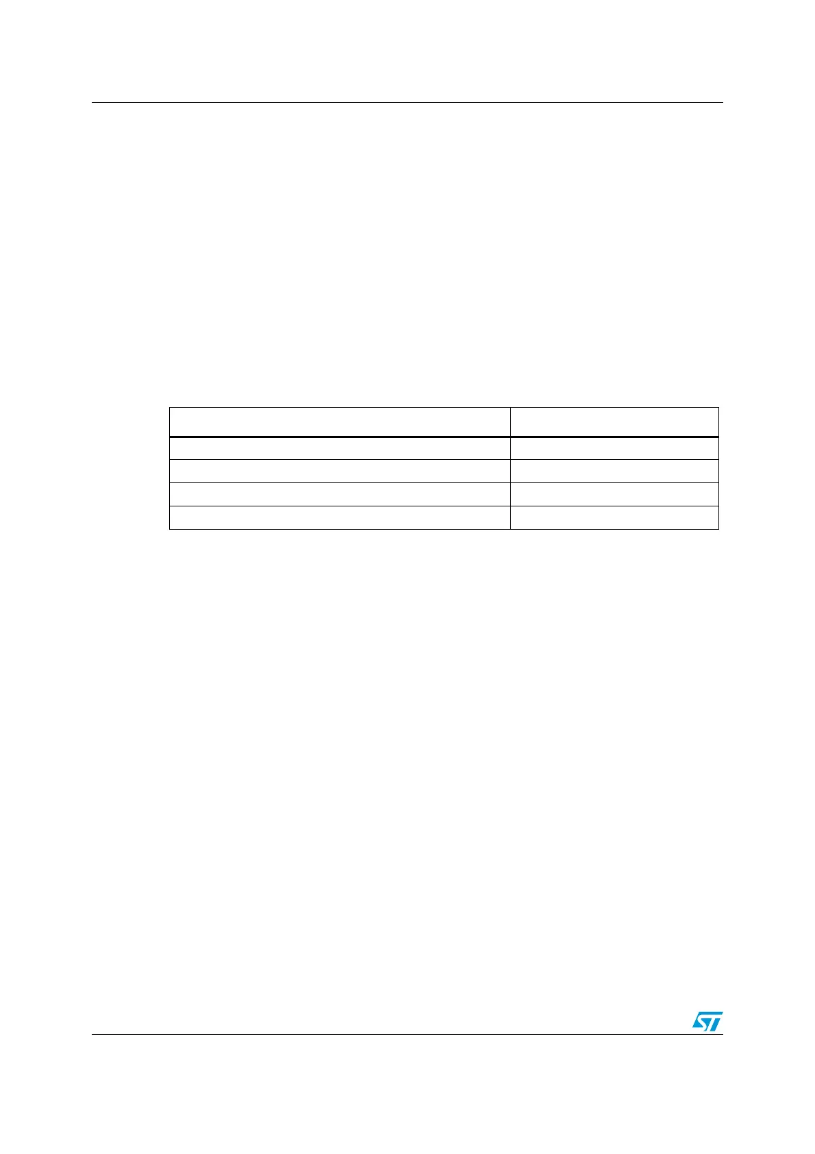
Table 50. Configuring the trigger polarity
Source EXTEN[1:0] / JEXTEN[1:0]
Trigger detection disabled 00
Detection on the rising edge 01
Detection on the falling edge 10
Detection on both the rising and falling edges 11

 Loading...


