RM0090 General-purpose timers (TIM2 to TIM5)
Doc ID 018909 Rev 4 444/1422
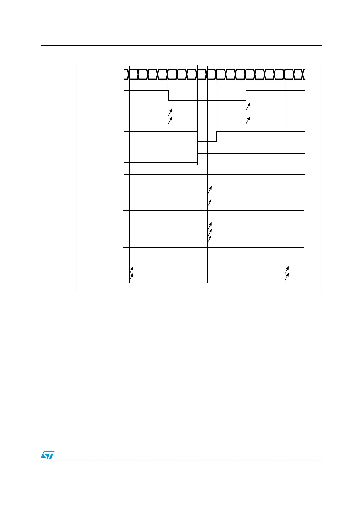
Figure 150. Center-aligned PWM waveforms (ARR=8)
Hints on using center-aligned mode:
● When starting in center-aligned mode, the current up-down configuration is used. It
means that the counter counts up or down depending on the value written in the DIR bit
in the TIMx_CR1 register. Moreover, the DIR and CMS bits must not be changed at the
same time by the software.
● Writing to the counter while running in center-aligned mode is not recommended as it
can lead to unexpected results. In particular:
– The direction is not updated if you write a value in the counter that is greater than
the auto-reload value (TIMx_CNT>TIMx_ARR). For example, if the counter was
counting up, it continues to count up.
– The direction is updated if you write 0 or write the TIMx_ARR value in the counter
but no Update Event UEV is generated.
● The safest way to use center-aligned mode is to generate an update by software
(setting the UG bit in the TIMx_EGR register) just before starting the counter and not to
write the counter while it is running.
CCxIF
012345678765432101Counter register
CCRx = 4
OCxREF
CMS=01
CMS=10
CMS=11
CCxIF
CCRx = 7
OCxREF
CMS=10 or 11
CCxIF
CCRx = 8
OCxREF
CMS=01
CMS=10
CMS=11
'1'
CCxIF
CCRx > 8
OCxREF
CMS=01
CMS=10
CMS=11
'1'
CCxIF
CCRx = 0
OCxREF
CMS=01
CMS=10
CMS=11
'0'
ai14681b

 Loading...


