General-purpose I/Os (GPIO) RM0090
191/1422 Doc ID 018909 Rev 4
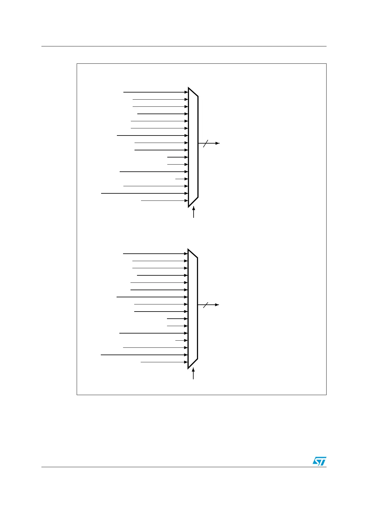
Figure 19. Selecting an alternate function on STM32F42xxx and STM32F43xxx
1. Configured in FS.
7.3.3 I/O port control registers
Each of the GPIOs has four 32-bit memory-mapped control registers (GPIOx_MODER,
GPIOx_OTYPER, GPIOx_OSPEEDR, GPIOx_PUPDR) to configure up to 16 I/Os. The
GPIOx_MODER register is used to select the I/O direction (input, output, AF, analog). The
MS30435V1
For pins 0 to 7, the GPIOx_AFRL[31:0] register selects the dedicated alternate function
AF0 (system)
AF1 (TIM1/TIM2)
AF2 (TIM3..5)
AF3 (TIM8..11)
AF4 (I2C1..3)
AF5 (SPI1/2/4/5/6)
AF6 (SPI3)
AF7 (USART1..3)
AF8 (USART4..8)
AF9 (CAN1/CAN2, TIM12..14)
AF10 (OTG_FS, OTG_HS)
AF11 (ETH)
AF12 (FSMC, SDIO, OTG_HS
(1)
)
AF13 (DCMI)
AF14
AF15 (EVENTOUT)
Pin x (x = 0..7)
AFRL[31:0]
For pins 8 to 15, the GPIOx_AFRH[31:0] register selects the dedicated alternate function
AF0 (system)
AF1 (TIM1/TIM2)
AF2 (TIM3..5)
AF3 (TIM8..11)
AF4 (I2C1..3)
AF5 (SPI1/2/4/5/6)
AF6 (SPI3)
AF7 (USART1..3)
AF8 (USART4..8)
AF9 (CAN1/CAN2, TIM12..14)
AF10 (OTG_FS, OTG_HS)
AF11 (ETH)
AF12 (FSMC, SDIO, OTG_HS
(1)
)
AF13 (DCMI)
AF14
AF15 (EVENTOUT)
Pin x (x = 8..15)
AFRH[31:0]
1
1

 Loading...


