General-purpose timers (TIM9 to TIM14) RM0090
497/1422 Doc ID 018909 Rev 4
Figure 183. Edge-aligned PWM waveforms (ARR=8)
16.4.10 One-pulse mode
One-pulse mode (OPM) is a particular case of the previous modes. It allows the counter to
be started in response to a stimulus and to generate a pulse with a programmable length
after a programmable delay.
Starting the counter can be controlled through the slave mode controller. Generating the
waveform can be done in output compare mode or PWM mode. You select One-pulse mode
by setting the OPM bit in the TIMx_CR1 register. This makes the counter stop automatically
at the next update event UEV.
A pulse can be correctly generated only if the compare value is different from the counter
initial value. Before starting (when the timer is waiting for the trigger), the configuration must
be as follows:
CNT < CCRx≤ ARR (in particular, 0 < CCRx)
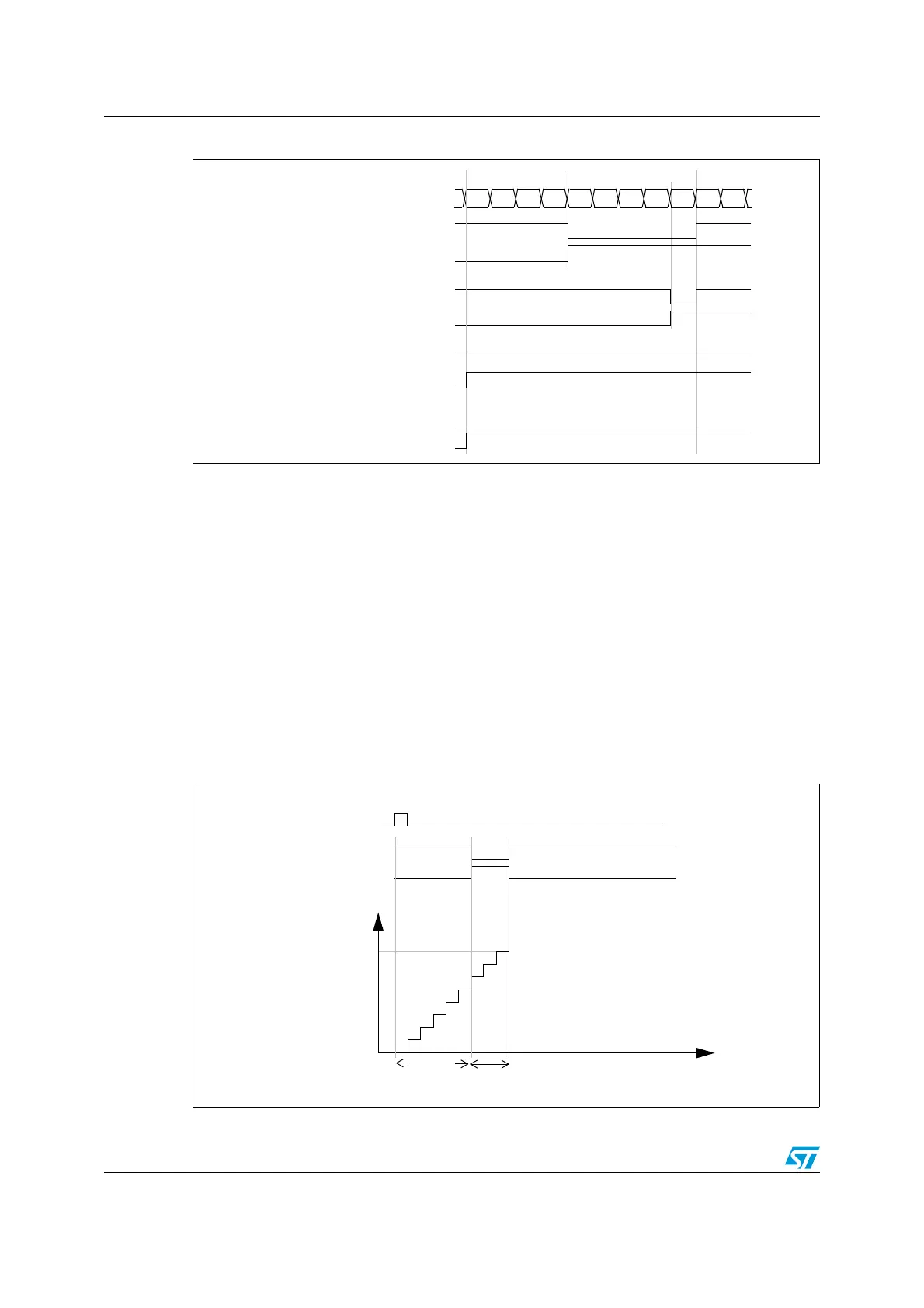
Figure 184. Example of one pulse mode.
Counter register
‘
0
1234567801
‘
OCXREF
CCxIF
OCXREF
CCxIF
OCXREF
CCxIF
OCXREF
CCxIF
CCRx=4
CCRx=8
CCRx>8
CCRx=0
TI2
OC1REF
Counter
t
0
TIM1_ARR
TIM1_CCR1
OC1
t
DELAY
t
PULSE

 Loading...


