USB on-the-go high-speed (OTG_HS) RM0090
1177/1422 Doc ID 018909 Rev 4
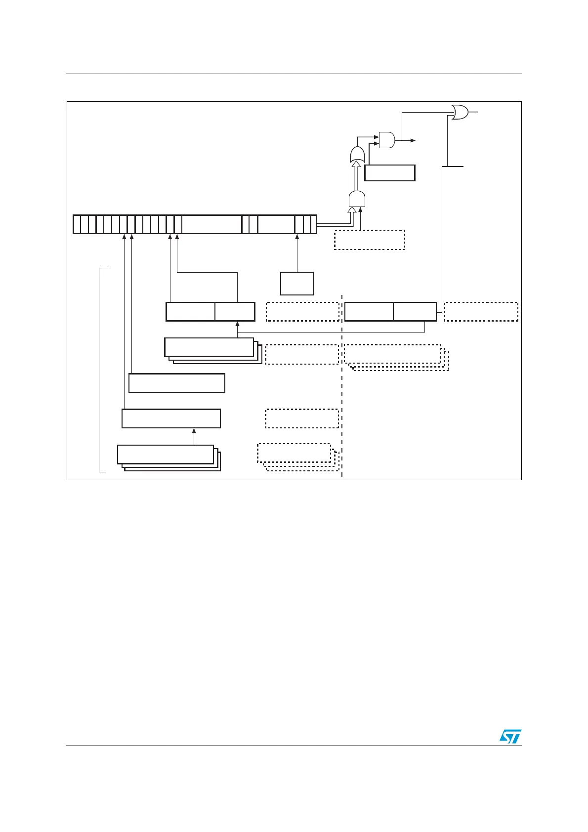
Figure 383. Interrupt hierarchy
1. The core interrupt register bits are shown in OTG_HS core interrupt register (OTG_HS_GINTSTS) on page 1194.
31.12 OTG_HS control and status registers
By reading from and writing to the control and status registers (CSRs) through the AHB
slave interface, the application controls the OTG_HS controller. These registers are 32 bits
31 30 29 28 27 26 25 24 23 20 19 18 17:10 9 8 7:3 210
AND
OR
Interrupt
Global interrupt
mask (Bit 0)
AHB configuration
register
Core interrupt mask
register
OTG
interrupt
register
Core interrupt
register
(1)
Device IN/OUT endpoint
interrupt registers 0 to 5
Device all endpoints
interrupt register
21:16
OUT endpoints
5:0
IN endpoints
Interrupt
sources
Host port control and status
register
Host all channels interrupt
register
Host channels interrupt
mask registers 0 to 11
Host all channels
interrupt mask register
Host channels interrupt
registers 0 to 11
22 21
Device all endpoints
interrupt mask register
Device IN/OUT
endpoints common
interrupt mask register
ai16093b
OR
AND
Device each IN/OUT endpoint
interrupt mask register
Device each endpoint
interrupt register
31:16
EP1OUT
15:0
EP1IN
Device each endpoint
interrupt mask register
endp_interrupt[31:0]
endp_multi_proc_intrpt

 Loading...


