USB on-the-go high-speed (OTG_HS) RM0090
1175/1422 Doc ID 018909 Rev 4
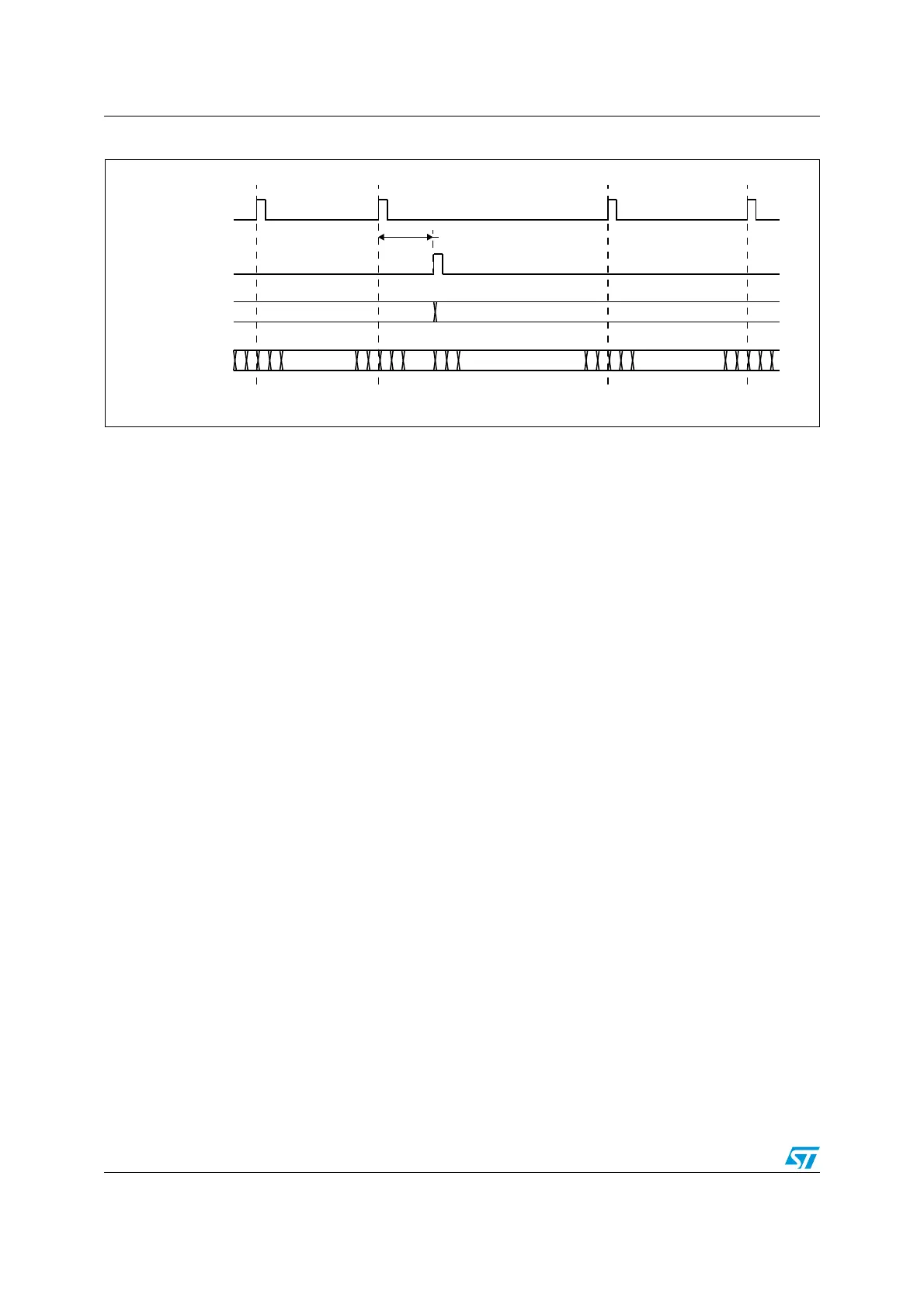
Figure 382. Updating OTG_HS_HFIR dynamically
31.10 FIFO RAM allocation
31.10.1 Peripheral mode
Receive FIFO RAM
For Receive FIFO RAM, the application should allocate RAM for SETUP packets: 10
locations must be reserved in the receive FIFO to receive SETUP packets on control
endpoints. These locations are reserved for SETUP packets and are not used by the core to
write any other data.
One location must be allocated for Global OUT NAK. Status information are also written to
the FIFO along with each received packet. Therefore, a minimum space of (Largest Packet
Size / 4) + 1 must be allocated to receive packets. If a high-bandwidth endpoint or multiple
isochronous endpoints are enabled, at least two spaces of (Largest Packet Size / 4) + 1
must be allotted to receive back-to-back packets. Typically, two (Largest Packet Size / 4) + 1
spaces are recommended so that when the previous packet is being transferred to AHB, the
USB can receive the subsequent packet.
Along with each endpoints last packet, transfer complete status information are also pushed
to the FIFO. Typically, one location for each OUT endpoint is recommended.
Transmit FIFO RAM
For Transmit FIFO RAM, the minimum RAM space required for each IN Endpoint Transmit
FIFO is the maximum packet size for this IN endpoint.
Note: More space allocated in the transmit IN Endpoint FIFO results in a better performance on
the USB.
31.10.2 Host mode
Receive FIFO RAM
For Receive FIFO RAM allocation, Status information are written to the FIFO along with
each received packet. Therefore, a minimum space of (Largest Packet Size / 4) + 1 must be
allocated to receive packets. If a high-bandwidth channel or multiple isochronous channels
400
…
…
… ……
450
Latency
SOF
reload
OTG_HS_HFIR
write
value
Frame
timer
Old OTG_HS_HIFR value
= 400 periods
OTG_HS_HIFR value
= 450 periods+HIFR write latency
New OTG_HS_HIFR value
= 450 periods
1
400
0
399
1
400
0
399
450
449
1
450
0
449
1
450
0
449
OTG_HS_HFIR
ai18439b

 Loading...


