RM0090 DMA controller (DMA)
Doc ID 018909 Rev 4 232/1422
be forced by hardware to 0xFFFF as soon as the stream is enabled, to respect the following
schemes:
● Anticipated stream interruption: EN bit in DMA_SxCR register is reset to 0 by the
software to stop the stream before the last data hardware signal (single or burst) is sent
by the peripheral. In such a case, the stream is switched off and the FIFO flush is
triggered in the case of a peripheral-to-memory DMA transfer. The TCIFx flag of the
corresponding stream is set in the status register to indicate the DMA completion. To
know the number of data items transferred during the DMA transfer, read the
DMA_SxNDTR register and apply the following formula:
– Number_of_data_transferred = 0xFFFF – DMA_SxNDTR
● Normal stream interruption due to the reception of a last data hardware signal: the
stream is automatically interrupted when the peripheral requests the last transfer
(single or burst) and when this transfer is complete. the TCIFx flag of the corresponding
stream is set in the status register to indicate the DMA transfer completion. To know the
number of data items transferred, read the DMA_SxNDTR register and apply the same
formula as above.
● The DMA_SxNDTR register reaches 0: the TCIFx flag of the corresponding stream is
set in the status register to indicate the forced DMA transfer completion. The stream is
automatically switched off even though the last data hardware signal (single or burst)
has not been yet asserted. The already transferred data will not be lost. This means
that a maximum of 65535 data items can be managed by the DMA in a single
transaction, even in peripheral flow control mode.
Note: When configured in memory-to-memory mode, the DMA is always the flow controller and
the PFCTRL bit is forced to 0 by hardware.
The Circular mode is forbidden in the peripheral flow controller mode.
9.3.16 Summary of the possible DMA configurations
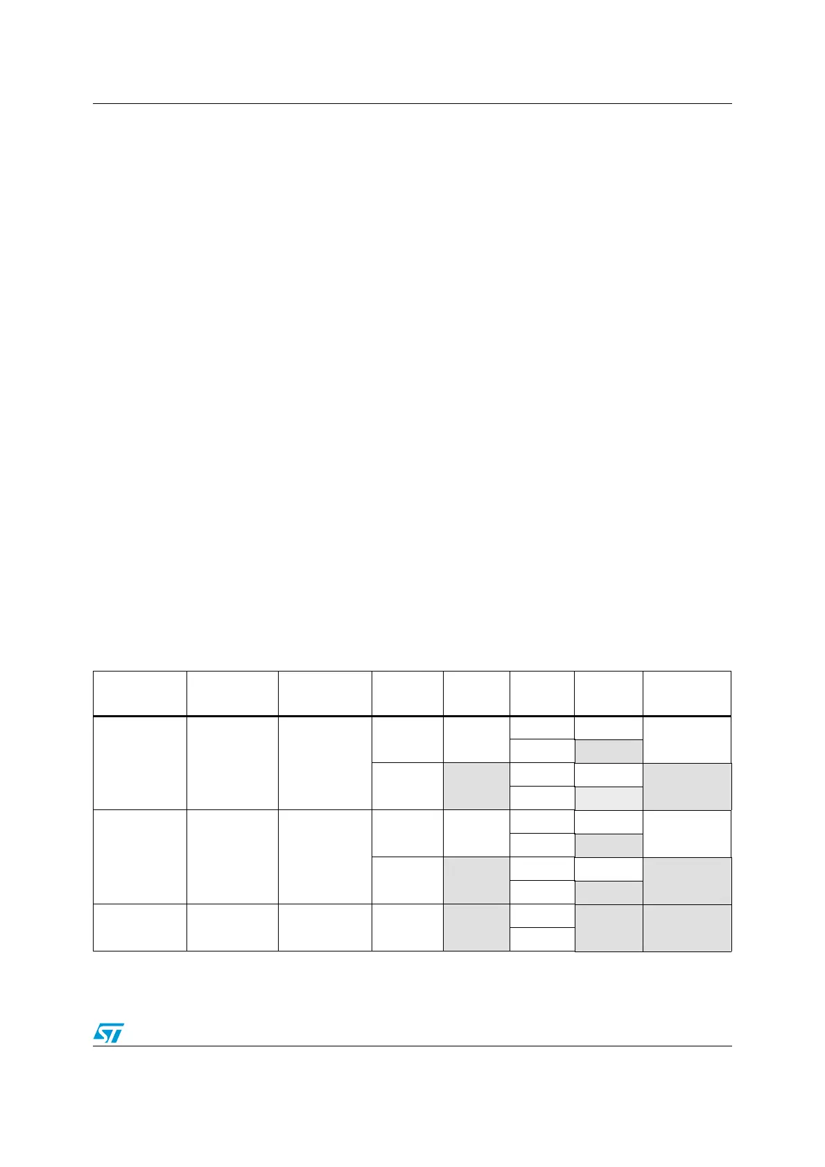
Tabl e 4 2 summarizes the different possible DMA configurations.
Table 42. Possible DMA configurations
DMA transfer
mode
Source Destination
Flow
controller
Circular
mode
Transfer
type
Direct
mode
Double
buffer mode
Peripheral-to-
memory
AHB
peripheral port
AHB
memory port
DMA possible
single possible
possible
burst
forbidden
Peripheral
forbidden
single possible
forbidden
burst
forbidden
Memory-to-
peripheral
AHB
memory port
AHB
peripheral port
DMA possible
single possible
possible
burst
forbidden
Peripheral
forbidden
single possible
forbidden
burst forbidden
Memory-to-
memory
AHB
peripheral port
AHB
memory port
DMA only
forbidden
single
forbidden forbidden
burst

 Loading...


