Power controller (PWR) RM0090
105/1422 Doc ID 018909 Rev 4
5.4 Power control registers
5.4.1 PWR power control register (PWR_CR)
for STM32F405xx/07xx and STM32F415xx/17xx
Address offset: 0x00
Reset value: 0x0000 4000 (reset by wakeup from Standby mode)
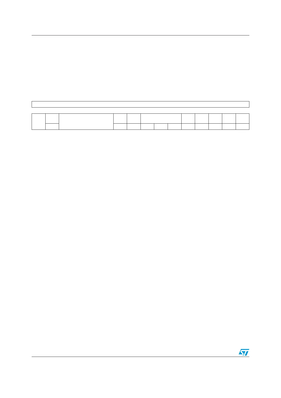
31 30 29 28 27 26 25 24 23 22 21 20 19 18 17 16
Reserved
1514131211109876543210
Res.
VOS
Reserved
FPDS DBP PLS[2:0] PVDE CSBF CWUF PDDS LPDS
rw rw rw rw rw rw rw rc_w1 rc_w1 rw rw
Bits 31:15 Reserved, must be kept at reset value.
Bit 14 VOS: Regulator voltage scaling output selection
This bit controls the main internal voltage regulator output voltage to achieve a trade-off
between performance and power consumption when the device does not operate at the
maximum frequency.
0: Scale 2 mode
1: Scale 1 mode (default value at reset)
Bits 13:10 Reserved, must be kept at reset value.
Bit 9 FPDS: Flash power-down in Stop mode
When set, the Flash memory enters power-down mode when the device enters Stop mode.
This allows to achieve a lower consumption in stop mode but a longer restart time.
0: Flash memory not in power-down when the device is in Stop mode
1: Flash memory in power-down when the device is in Stop mode
Bit 8 DBP: Disable backup domain write protection
In reset state, the RCC_BDCR register, the RTC registers (including the backup registers), and
the BRE bit of the PWR_CSR register, are protected against parasitic write access. This bit
must be set to enable write access to these registers.
0: Access to RTC and RTC Backup registers and backup SRAM disabled
1: Access to RTC and RTC Backup registers and backup SRAM enabled
Bits 7:5 PLS[2:0]: PVD level selection
These bits are written by software to select the voltage threshold detected by the Power
Voltage Detector
000: 2.0 V
001: 2.1 V
010: 2.3 V
011: 2.5 V
100: 2.6 V
101: 2.7 V
110: 2.8 V
111: 2.9 V
Note: Refer to the electrical characteristics of the datasheet for more details.

 Loading...


