Controller area network (bxCAN) RM0090
665/1422 Doc ID 018909 Rev 4
Dual CAN
● CAN1: Master bxCAN for managing the communication between a Slave bxCAN and
the 512-byte SRAM memory
● CAN2: Slave bxCAN, with no direct access to the SRAM memory.
● The two bxCAN cells share the 512-byte SRAM memory (see Figure 224: Dual CAN
block diagram)
Dual CAN
● CAN1: Master bxCAN for managing the communication between a Slave bxCAN and
the 512-byte SRAM memory
● CAN2: Slave bxCAN, with no direct access to the SRAM memory.
● The two bxCAN cells share the 512-byte SRAM memory (see Figure 224 on page 667)
24.3 bxCAN general description
In today’s CAN applications, the number of nodes in a network is increasing and often
several networks are linked together via gateways. Typically the number of messages in the
system (and thus to be handled by each node) has significantly increased. In addition to the
application messages, Network Management and Diagnostic messages have been
introduced.
● An enhanced filtering mechanism is required to handle each type of message.
Furthermore, application tasks require more CPU time, therefore real-time constraints
caused by message reception have to be reduced.
● A receive FIFO scheme allows the CPU to be dedicated to application tasks for a long
time period without losing messages.
The standard HLP (Higher Layer Protocol) based on standard CAN drivers requires an
efficient interface to the CAN controller.
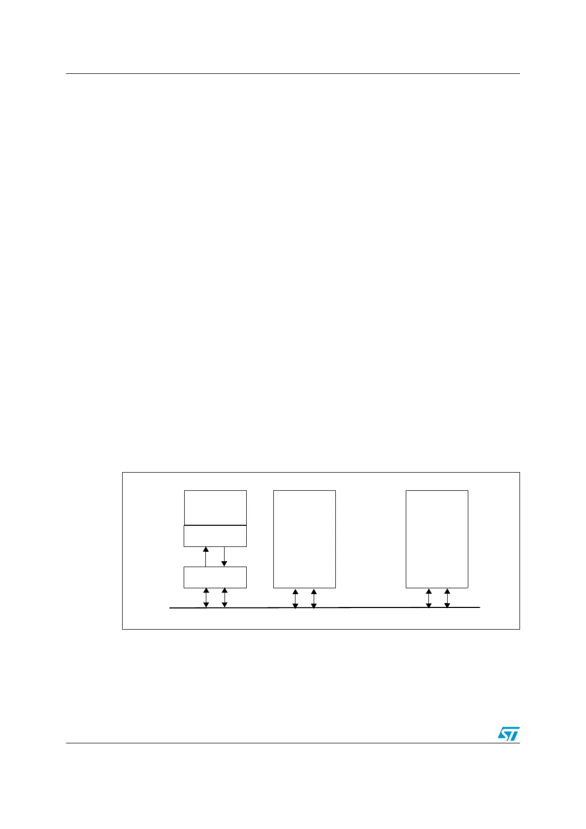
Figure 223. CAN network topology
24.3.1 CAN 2.0B active core
The bxCAN module handles the transmission and the reception of CAN messages fully
autonomously. Standard identifiers (11-bit) and extended identifiers (29-bit) are fully
supported by hardware.
CAN node 1
CAN node 2
CAN node n
CANCAN
High
Low
CANCAN
Rx Tx
CAN
Transceiver
CAN
Controller
MCU
CAN Bus
Application

 Loading...


