RM0090 Basic timers (TIM6&TIM7)
Doc ID 018909 Rev 4 530/1422
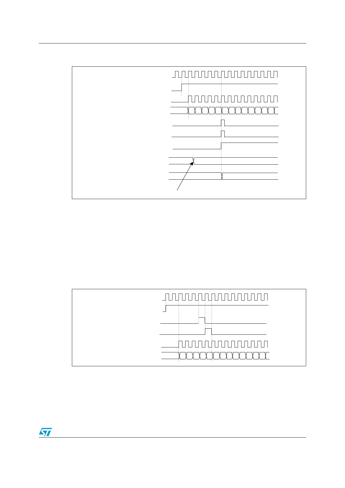
Figure 196. Counter timing diagram, update event when ARPE=1 (TIMx_ARR
preloaded)
17.3.3 Clock source
The counter clock is provided by the Internal clock (CK_INT) source.
The CEN (in the TIMx_CR1 register) and UG bits (in the TIMx_EGR register) are actual
control bits and can be changed only by software (except for UG that remains cleared
automatically). As soon as the CEN bit is written to 1, the prescaler is clocked by the internal
clock CK_INT.
Figure 197 shows the behavior of the control circuit and the upcounter in normal mode,
without prescaler.
Figure 197. Control circuit in normal mode, internal clock divided by 1
17.3.4 Debug mode
When the microcontroller enters the debug mode (Cortex™-M4F core - halted), the TIMx
counter either continues to work normally or stops, depending on the DBG_TIMx_STOP
configuration bit in the DBG module. For more details, refer to Section 33.16.2: Debug
support for timers, watchdog, bxCAN and I2C.
00
CNT_EN
Timer clock = CK_CNT
Counter register
Update interrupt flag (UIF)
Counter overflow
Update event (UEV)
01 02 03 04 05 06 07F1 F2 F3 F4 F5F0
Auto-reload preload register
F5 36
Auto-reload shadow register
F5 36
Write a new value in TIMx_ARR
CK_PSC
CK_INT
00
Counter clock = CK_CNT = CK_PSC
Counter register
01 02 03 04 05 06 0732 33 34 35 3631
CEN=CNT_EN
UG
CNT_INIT

 Loading...


