Advanced-control timers (TIM1&TIM8) RM0090
393/1422 Doc ID 018909 Rev 4
2. Configure the channel 1 as follows, to detect rising edges on TI:
– IC1F=0000: no filter.
– The capture prescaler is not used for triggering and does not need to be
configured.
– CC1S=01 in TIMx_CCMR1 register to select only the input capture source
– CC1P=0 and CC1NP=’0’ in TIMx_CCER register to validate the polarity (and
detect rising edge only).
3. Configure the timer in trigger mode by writing SMS=110 in TIMx_SMCR register. Select
TI1 as the input source by writing TS=101 in TIMx_SMCR register.
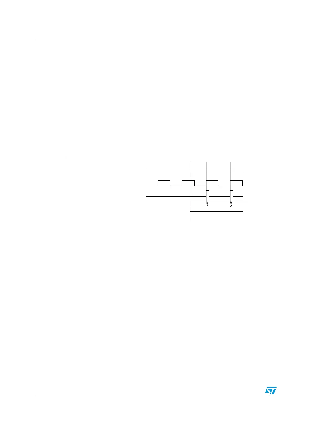
A rising edge on TI1 enables the counter and sets the TIF flag. The counter then counts on
ETR rising edges.
The delay between the rising edge of the ETR signal and the actual reset of the counter is
due to the resynchronization circuit on ETRP input.
Figure 118. Control circuit in external clock mode 2 + trigger mode
14.3.20 Timer synchronization
The TIM timers are linked together internally for timer synchronization or chaining. Refer to
Section 15.3.15: Timer synchronization on page 453 for details.
14.3.21 Debug mode
When the microcontroller enters debug mode (Cortex™-M4F core halted), the TIMx counter
either continues to work normally or stops, depending on DBG_TIMx_STOP configuration
bit in DBG module. For more details, refer to Section 33.16.2: Debug support for timers,
watchdog, bxCAN and I2C.
Counter clock = CK_CNT = CK_PSC
Counter register
35 3634
ETR
CEN/CNT_EN
TIF
TI1

 Loading...


