Routine Maintenance Procedures
555-233-123
5-16 Issue 4 May 2002
Replacing a TN736 or TN752 power unit circuit
pack
Replacing either power unit interrupts the -5 volt supply to the carrier. This causes
all the analog circuit packs in the carrier to fail their Loop Around Tests and may
cause failures in circuit packs in the control complex. After the power unit has
been replaced, look for these alarms:
■ ANL-LINE alarms — refer to Test #47 (Loop Around and Conference Test)
in ‘‘ANL-LINE (8-Port Analog Line), ANL-NE-L (8-Port Neon Analog Line)’’.
■ CO-TRK alarms — refer to Test #33 (Loop Around and Conference Test) in
‘‘CO-TRK (CO Trunk)’’.
All other power supplies
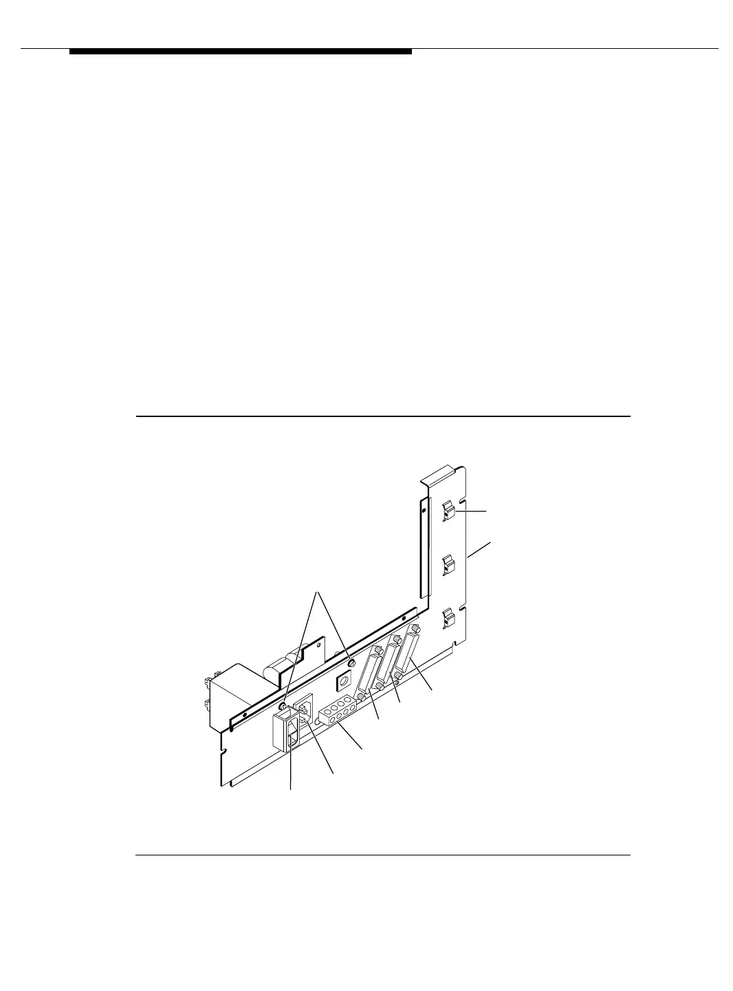
Figure 5-3 on page 5-16 and Figure 5-4 on page 5-17 provide views of the power
supply sub-assembly. Figure 5-5 on page 5-18 provides a view of the fan
sub-assembly. The sections following the figures discuss how to disassemble the
unit and then replace the power supply or fans within the unit.
Figure 5-3. Power supply sub-assembly (outside view)
Screw
Cable
Retainer
Power
Panel
DCE
Connector
PI
Connector
Ground
Block
Power Cord
Receptacle
Term
Connector
On/Off
Switch