MPC5604B/C Microcontroller Reference Manual, Rev. 8
130 Freescale Semiconductor
7.6.2 Output Clock Multiplexing
The MC_CGM contains a multiplexing function for a number of clock sources which can then be utilized
as output clock sources. The selection is done via the CGM_OCDS_SC register.
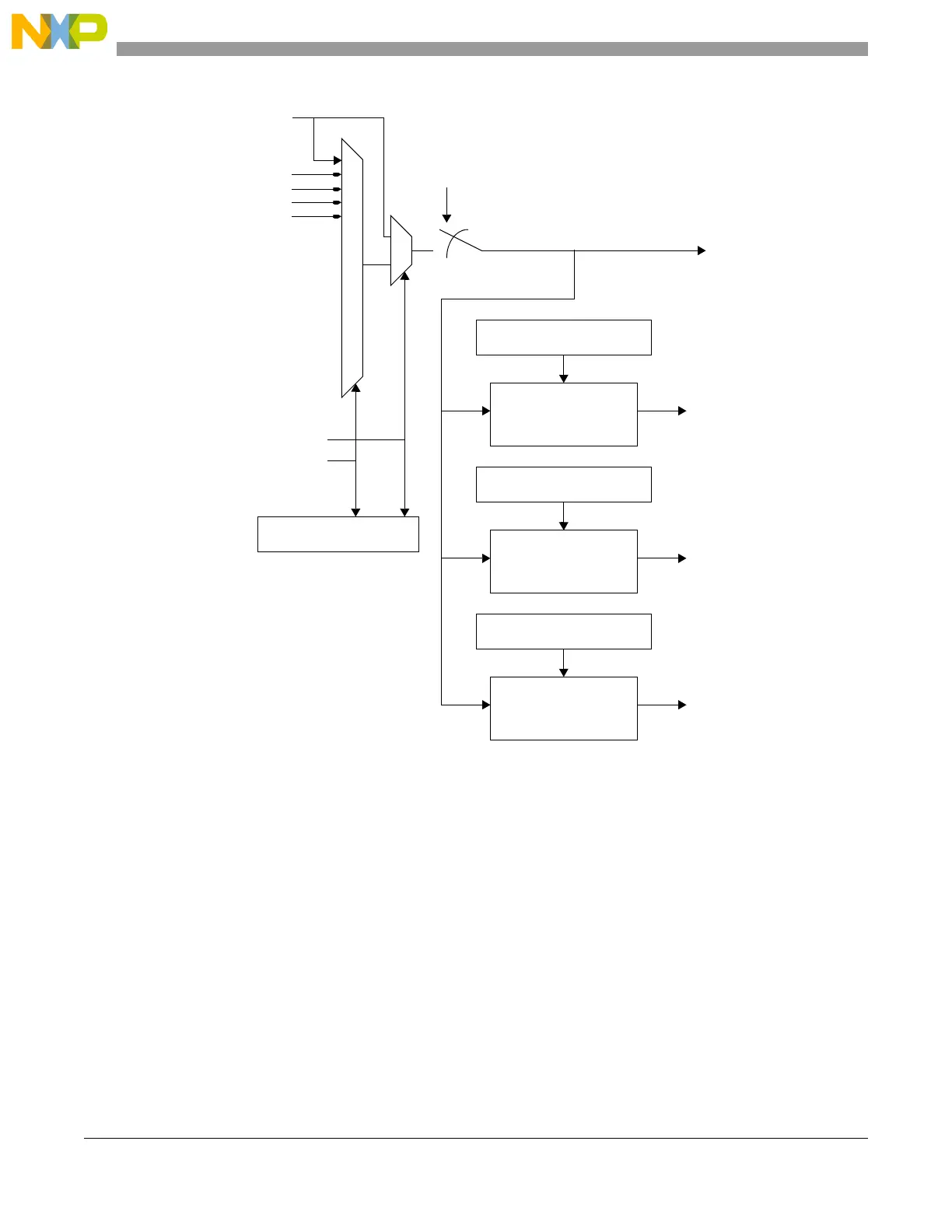
Figure 7-6. MC_CGM System Clock Generation Overview
16 MHz int. RC osc.
4-16 MHz ext. xtal osc. 2
div. ext. xtal osc. 3
freq. mod. PLL 4
div. 16 MHz int. RC osc. 1
0
system clock
’0’
system clock is disabled if
ME_<current mode>_MC.SYSCLK = “1111”
CGM_SC_SS Register
MC_RGM safe clock request
MC_ME clock select
1
0
CGM_SC_DC0 Register
clock divider
peripheral set 1 clock
CGM_SC_DC1 Register
clock divider
peripheral set 2 clock
CGM_SC_DC2 Register
clock divider
peripheral set 3 clock