MPC5604B/C Microcontroller Reference Manual, Rev. 8
Freescale Semiconductor 497
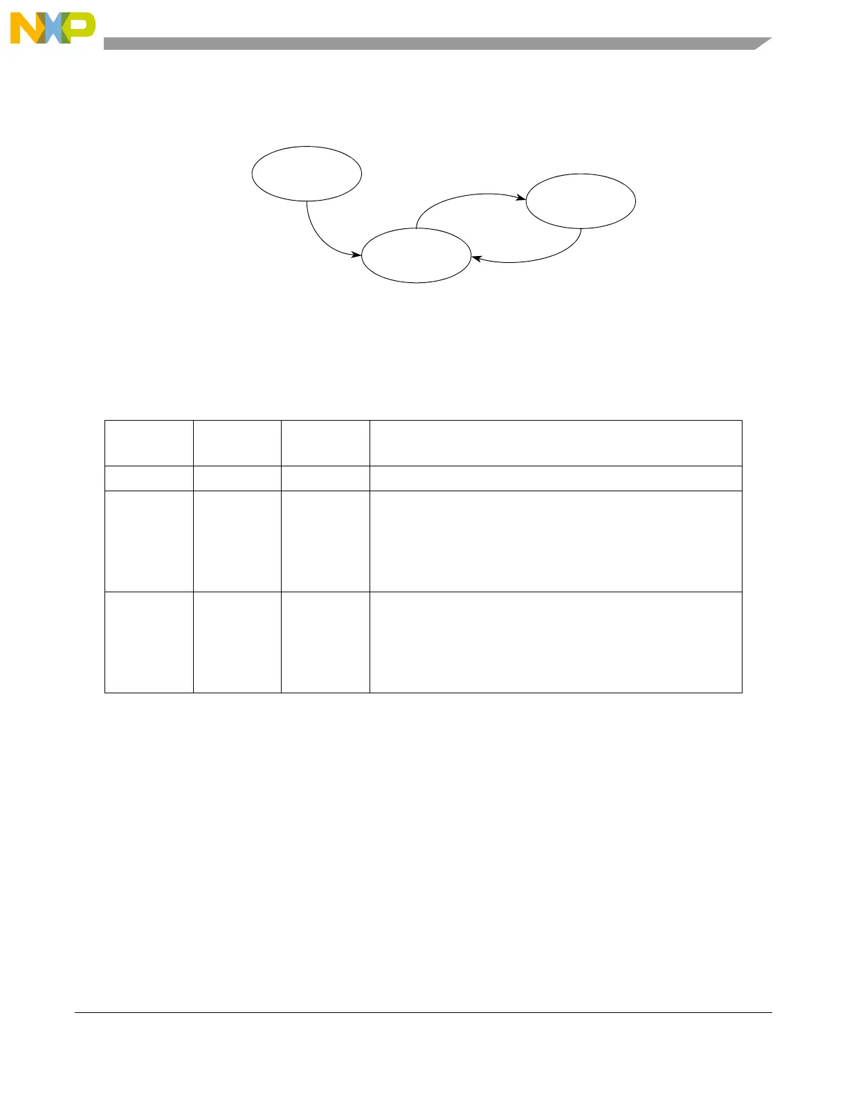
Figure 23-13. DSPI start and stop state diagram
The transitions are described in Table 23-24.
State transitions from RUNNING to STOPPED occur on the next frame boundary if a transfer is in
progress, or on the next system clock cycle if no transfers are in progress.
23.6.3 Serial peripheral interface (SPI) configuration
The SPI configuration transfers data serially using a shift register and a selection of programmable transfer
attributes. The DSPI is in SPI configuration when the DCONF field in the DSPIx_MCR is 0b00. The SPI
frames can be from 4 to 16 bits long. The data to be transmitted can come from queues stored in SRAM
external to the DSPI. Host software can transfer the SPI data from the queues to a first-in first-out (FIFO)
buffer. The received data is stored in entries in the receive FIFO (RX FIFO) buffer. Host software transfers
the received data from the RX FIFO to memory external to the DSPI.
The FIFO buffer operations are described in Section 23.6.3.4, Transmit First In First Out (TX FIFO)
buffering mechanism, and Section 23.6.3.5, Receive First In First Out (RX FIFO) buffering mechanism.
Table 23-24. State transitions for start and stop of DSPI transfers
Transition
No.
Current state Next state Description
0 RESET STOPPED Generic power-on-reset transition
1 STOPPED RUNNING The DSPI starts (transitions from STOPPED to RUNNING) when all
of the following conditions are true:
• EOQF bit is clear
• Debug mode is unselected or the FRZ bit is clear
• HALT bit is clear
2 RUNNING STOPPED The DSPI stops (transitions from RUNNING to STOPPED) after the
current frame for any one of the following conditions:
• EOQF bit is set
• Debug mode is selected and the FRZ bit is set
• HALT bit is set
RUNNING
TXRXS = 1
STOPPED
TXRXS = 0
RESET
Power-on-Reset 0
1
2