MPC5604B/C Microcontroller Reference Manual, Rev. 8
592 Freescale Semiconductor
25.1.2 Device-specific implementation
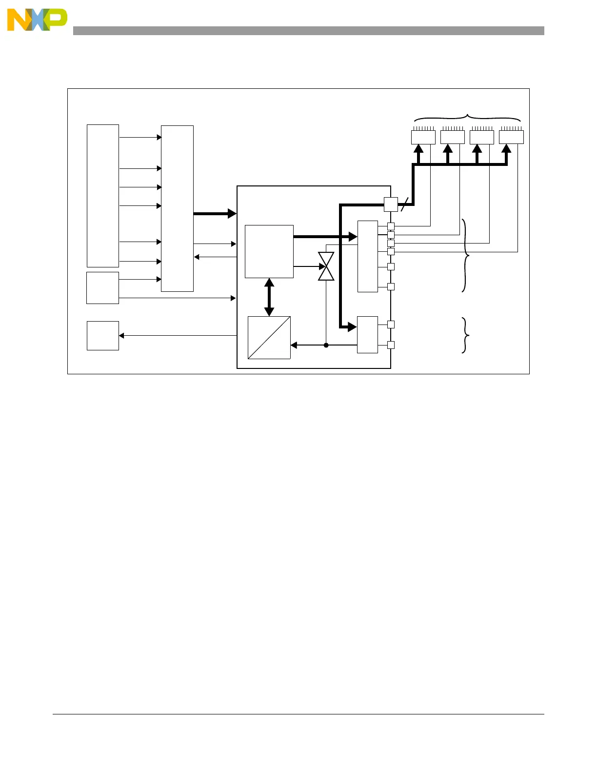
Figure 25-1. ADC implementation
25.2 Introduction
The analog-to-digital converter (ADC) block provides accurate and fast conversions for a wide range of
applications.
The ADC contains advanced features for normal or injected conversion. A conversion can be triggered by
software or hardware (Cross Triggering Unit or PIT).
There are three types of input channels:
• Internal precision, ADC0_P[n] (internally multiplexed precision channels)
• Internal standard, ADC0_S[n] (internally multiplexed standard channels)
• External ADC0_X[n] (externally multiplexed standard channels)
The mask registers present within the ADC can be programmed to configure which channel has to be
converted.
Three external decode signals MA[2:0] (multiplexer address) are provided for external channel selection
and are available as alternate functions on GPIO.
The MA[0:2] are controlled by the ADC itself and are set automatically by the hardware.
A conversion timing register for configuring different sampling and conversion times is associated to each
channel type.
PIT2
CTU
eMIOS
PIT
Ch23 trig
PIT3
ADC control
ADC trigger
ADC done
2 interrupts
ADC_EOC & ADC_WD
Digital
Interface
Analog
switch
INTC
D
A
MUX 20
MUX 16
ADC_0 (10 bit)
eMIOS0_0
eMIOS0_22
eMIOS0_24
Ch0 trig
Ch22 trig
Ch24 trig
eMIOS1_0
eMIOS1_22
eMIOS1_24
Ch32 trig
Ch54 trig
Ch56 trig
.
.
.
.
.
.
.
.
.
.
.
.
Up to 20
standard channels
16 precision
ADC0_X[3]
ADC0_X[0]
ADC0_S[15] (Ch 47)
ADC0_S[0] (Ch 32)
ADC0_P[15] (Ch 15)
ADC0_P[0] (Ch 0)
MA[2:0]
MUX 8
MUX 8
3
.
.
.
.
.
.
ADC0_X[2]
ADC0_X[1]
MUX 8
MUX 8
(Ch 88–95)
(Ch 64–71)
(Ch 80–87)
(Ch 72–79)
channels
Up to 32 extended channels
through external MUX
 Loading...