MPC5604B/C Microcontroller Reference Manual, Rev. 8
Freescale Semiconductor 631
Chapter 26
Cross Triggering Unit (CTU)
26.1 Introduction
The Cross Triggering Unit (CTU) allows to synchronize an ADC conversion with a timer event from
eMIOS (every mode which can generate a DMA request can trigger CTU) or PIT. To select which ADC
channel must be converted on a particular timer event, the CTU provides the ADC with a 7-bit channel
number. This channel number can be configured for each timer channel event by the application.
26.2 Main features
• Single cycle delayed trigger output. The trigger output is a combination of 64 (generic value) input
flags/events connected to different timers in the system.
• One event configuration register dedicated to each timer event allows to define the corresponding
ADC channel.
• Acknowledgment signal to eMIOS/PIT for clearing the flag
• Synchronization with ADC to avoid collision
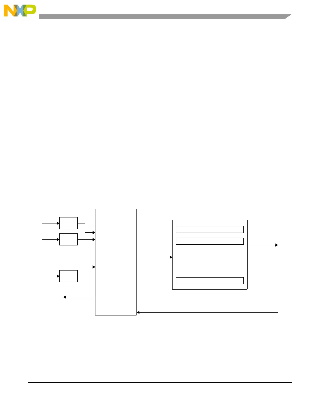
26.3 Block diagram
The CTU block diagram is shown in Figure 26-1.
Figure 26-1. Cross Triggering Unit block diagram
26.4 Memory map and register descriptions
The CTU registers are listed in Table 26-1. Every register can have 32-bit access. The base address of the
CTU is 0xFFE6_4000.
Event
Gen
Event
Gen
Event
Gen
FLAG_ACK
NEXT_CMD
Channel value select
Tri g0
Tri g1
Tr ig 63
Channel value
Event
Arbitration
&
Masking
Event Configuration Register 0
Event Configuration Register 1
Event Configuration Register 63
.
.
.
.
.
.
.
.
.
.