MPC5604B/C Microcontroller Reference Manual, Rev. 8
528 Freescale Semiconductor
• One 32-bit up counter with 8-bit prescaler
• Four 32-bit compare channels
• Independent interrupt source for each channel
• Counter can be stopped in debug mode
24.3.1.3 Modes of operation
The STM supports two device modes of operation: normal and debug. When the STM is enabled in normal
mode, its counter runs continuously. In debug mode, operation of the counter is controlled by the FRZ bit
in the STM_CR register. If the FRZ bit is set, the counter is stopped in debug mode, otherwise it continues
to run.
24.3.2 External signal description
The STM does not have any external interface signals.
24.3.3 Memory map and register definition
The STM programming model has fourteen 32-bit registers. The STM registers can only be accessed using
32-bit (word) accesses. Attempted references using a different size or to a reserved address generates a bus
error termination.
24.3.3.1 Memory map
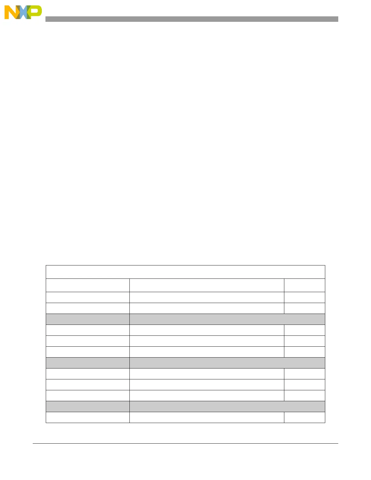
The STM memory map is shown in Table 24-3.
Table 24-3. STM memory map
Base address: 0xFFF3_C000
Address offset Register Location
0x0000 STM Control Register (STM_CR) on page 529
0x0004 STM Counter Value (STM_CNT) on page 530
0x0008–0x000C Reserved
0x0010 STM Channel 0 Control Register (STM_CCR0) on page 530
0x0014 STM Channel 0 Interrupt Register (STM_CIR0) on page 531
0x0018 STM Channel 0 Compare Register (STM_CMP0) on page 531
0x001C Reserved
0x0020 STM Channel 1 Control Register (STM_CCR1) on page 530
0x0024 STM Channel 1 Interrupt Register (STM_CIR1) on page 531
0x0028 STM Channel 1 Compare Register (STM_CMP1) on page 531
0x002C Reserved
0x0030 STM Channel 2 Control Register (STM_CCR2) on page 530